Working vehicle with cabin

a technology for working vehicles and cabins, applied in the direction of superstructures of loading-carrying vehicles, superstructure subunits, control devices, etc., can solve the problem of not being able to realize a stable support for cabins, and achieve the effect of reducing space and no deterioration of workability

Active Publication Date: 2012-11-20
YANMAR POWER TECHNOLOGY CO LTD
View PDF14 Cites 9 Cited by
  • Summary
  • Abstract
  • Description
  • Claims
  • Application Information

AI Technical Summary

Benefits of technology

[0008]The present invention has been achieved in view of this problem of the conventional art, and it is an object thereof to provide a working vehicle with cabin, in which rotational power from an engine is changed in speed by a transmission including a transmission case and is then transmitted to a pair of front wheels or a pair of rear wheels, which function as driving wheels, the working vehicle capable of realizing stabilization of support of the cabin with a simple structure.
[0010]The working vehicle according to the present invention makes it possible to improve the balance between the front and rear portions of the working vehicle 1, since the engine and the front axle case are disposed closer to the front side and the transmission is disposed closer to the rear side in the vehicle longitudinal direction. Further, since the cabin is supported in a vibration-isolation manner by highly rigid sites of the pair of main frames that are coupled with each other by the reinforcing member, and also by the transmission case or the rear axle cases, the configuration makes it also possible to enhance stabilization of support of the cabin, thereby realizing a desired antivibration effect for the cabin.
[0012]The configuration makes it possible to improve the rigidity of the supporting portions of the pair of main frames that support the cabin 8 via the attachment stays, in particular, the rigidity of the supporting portions around a central axis extending in the vehicle longitudinal direction. As a result, the cabin is stably supported.
[0014]According to the configuration, the front frame and the corresponding main frame are connected to each other at the overlapped region as well as are connected to each other through the engine. Therefore, the configuration makes it possible to have an effect of achieving easier handling thanks to adoption of a divisible structure of the vehicle frames including the front frames and the main frames that are detachably connected to each other, and also have an effect of preventing the deterioration in rigidity of the vehicle frames due to the divisible structure.
[0016]The configuration makes it possible to set a width (a distance in the vehicle width direction) between the pair of main frames freely and independently from a width between the pair of front frames.
[0019]The configuration makes it possible to realize the reduction in space with no deterioration of workability in assembling the brake operation link mechanism that includes the brake vertical links and the brake horizontal links.

Problems solved by technology

Accordingly, it is not possible to realize an enough stable support for the cabin.

Method used


Image

  • Working vehicle with cabin
  • Working vehicle with cabin
  • Working vehicle with cabin

Examples


Embodiment Construction

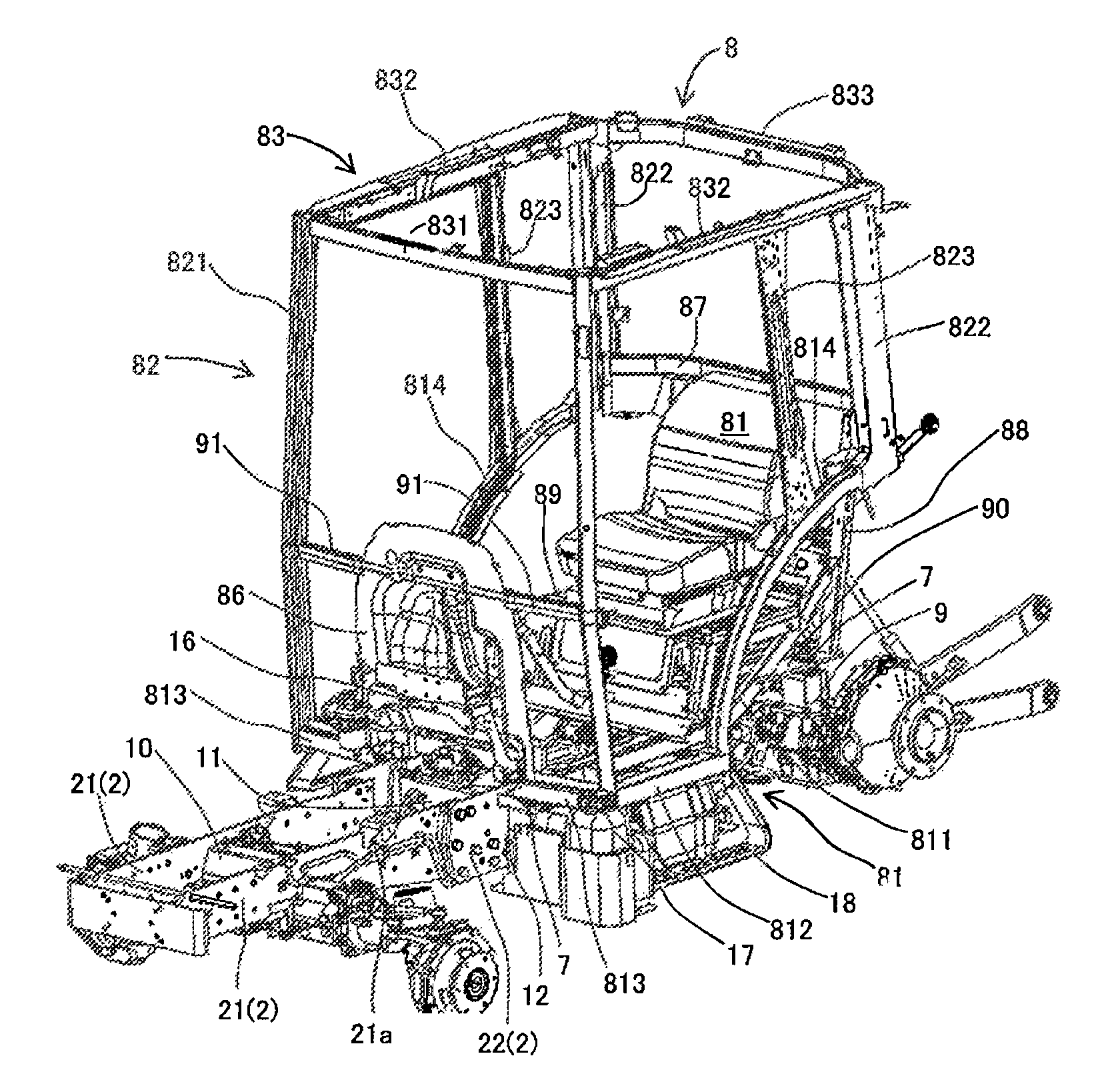
[0041]Described below is a working vehicle provided with a cabin according to a preferred embodiment of the present invention with reference to the accompanying drawings.

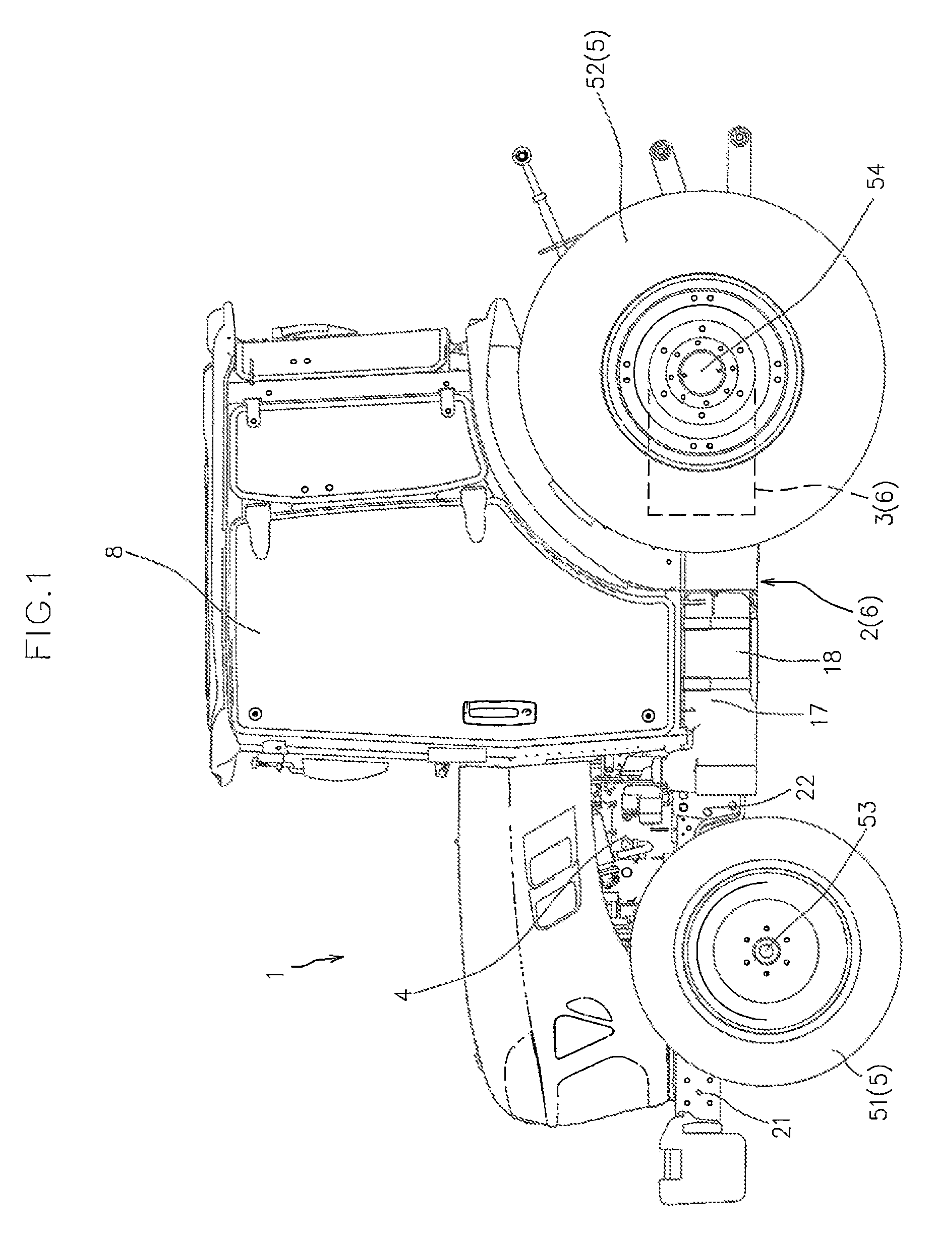
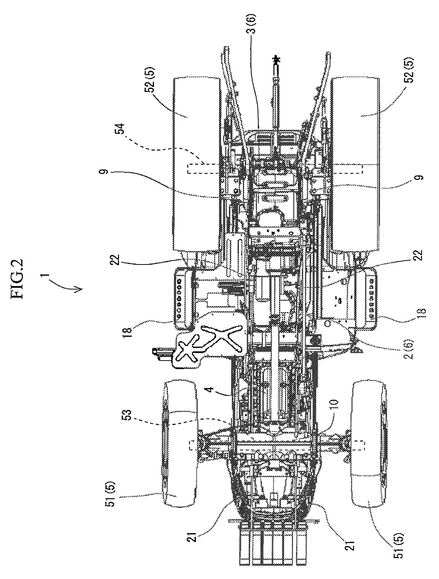
[0042]FIGS. 1 and 2 are left side view and a bottom view, respectively, of a working vehicle 1 according to an embodiment of the present invention.

[0043]As shown in FIG. 1, the working vehicle 1 is configured as a tractor to which a working device is mountable.

[0044]More specifically, as shown in FIGS. 1 and 2, the working vehicle 1 includes a pair of right and left vehicle frames 2 along a vehicle longitudinal direction, a transmission case 3 coupled to the rear ends of the vehicle frames 2, an engine 4 supported by the vehicle frames 2, and a pair of right and left traveling units 5.

[0045]In the present embodiment, the pair of right and left traveling units 5 have a pair of right and left front wheels 51 and a pair of right and left rear wheels 52.

[0046]The working vehicle 1 is configured such that rotational powe...


PUM


Abstract

A working vehicle according to the present invention includes a pair of front frames and a pair of main frames that are detachably connected to each other, a reinforcing member coupling the pair of main frames while being overlapped therewith in a side view, a pair of attachment stays fixedly attached to outer side surfaces of the pair of main frames so as to be at least partially overlapped with the reinforcing member in a side view. A cabin is supported in a vibration-isolation manner at no less than four positions including the pair of attachment stays and right and left supporting positions that are provided at a pair of rear axle cases or a transmission case. The working vehicle can enhance stabilization of support of the cabin while simplifying a structure.

Description

FIELD OF THE INVENTION[0001]The present invention relates to a working vehicle with cabin.BACKGROUND ART[0002]In working vehicles, rotational power from an engine is changed in speed at a transmission and is then transmitted to a pair of front wheels or a pair of rear wheels, which function as driving wheels. Among them, working vehicles each including a cabin that surrounds a driver's seat have been conventionally used as a tractor and the like.[0003]However, such a conventional working vehicle provided with a cabin has possibility for improvement in view of stably supporting the heavy cabin in a vibration-isolation manner.[0004]For example, in a conventional working vehicle provided with a cabin, a pair of front plates, a pair of cabin brackets, and four brackets for a transmission case at front, rear, right, and left positions are fixedly attached to front portions, intermediate portions, and rear portions of a pair of right and left main frames, respectively. The cabin is suppor...

Claims


Application Information

Patent Timeline
Patent Type & Authority Patents(United States)
IPC IPC(8): B62D21/00
CPCB62D21/186B62D24/02B62D33/0604B62D33/0617B62D25/20
Inventor KAWASHIRI, SHINYA
Owner YANMAR POWER TECHNOLOGY CO LTD
Why Eureka
Try Eureka