Illuminating device and image display device using the same

a technology of illumination device and image display device, which is applied in the direction of fixed installation, lighting and heating apparatus, instruments, etc., can solve the problems of deteriorating light efficiency, affecting the efficiency of light, and unable to quickly change the quantity of ligh

Inactive Publication Date: 2007-12-06
KYOCERA OPTEC +1
View PDF4 Cites 20 Cited by
  • Summary
  • Abstract
  • Description
  • Claims
  • Application Information

AI Technical Summary

Benefits of technology

[0035]The present invention, configured as described above, can provide an illuminating device that can perform high-speed light-adjustment control and an image display device using the same.

Problems solved by technology

In other words, it is required that the light source is kept lighted at a constant quantity of light and therefore, the quantity of light cannot quickly be changed.
In the foregoing mechanical illuminating device, when an aperture pivoting part is continuously and quickly pivoted forward and backward around a pivoting axis, it becomes a cause to raise mechanical vibration and acoustic noise by receiving influence of inertia of the aperture pivoting part.
Meanwhile, in the illuminating device in which the illuminating element is permanently provided in the light path of the illuminating optical system, because loss of passing light is inevitable, efficiency of light is deteriorated, whereby brightness is reduced.
However, when an artificial aperture is inserted into and removed from the light path of the illuminating optical system of a projection display device or the like, a light beam at an edge of an artifact, in other words, a light beam at a boundary portion between a dark image portion the light beam for which is cut off by the aperture and a bright image portion the light beam for which passes through the aperture without being cut off diffracts, thereby producing the difference in the light path length, whereby an aberration is caused.
When the aberration exceeds a given limitation, the aberration deteriorates the image quality of an image projected onto a screen and is perceived as color unevenness.
Moreover, the aperture pivoting part continuously and rapidly repeats the forward and backward movement around the pivoting axis, and design, in which the motor torque required for acceleration and forward-and-backward switching is made to have a enough margin for the inertia of the aperture pivoting part, is needed, and therefore, the voice coil, the magnetic circuit, the servo circuit, and the like become sizable, thereby making the downsizing of the illuminating device difficult.

Method used


Image

  • Illuminating device and image display device using the same
  • Illuminating device and image display device using the same
  • Illuminating device and image display device using the same

Examples


Embodiment Construction

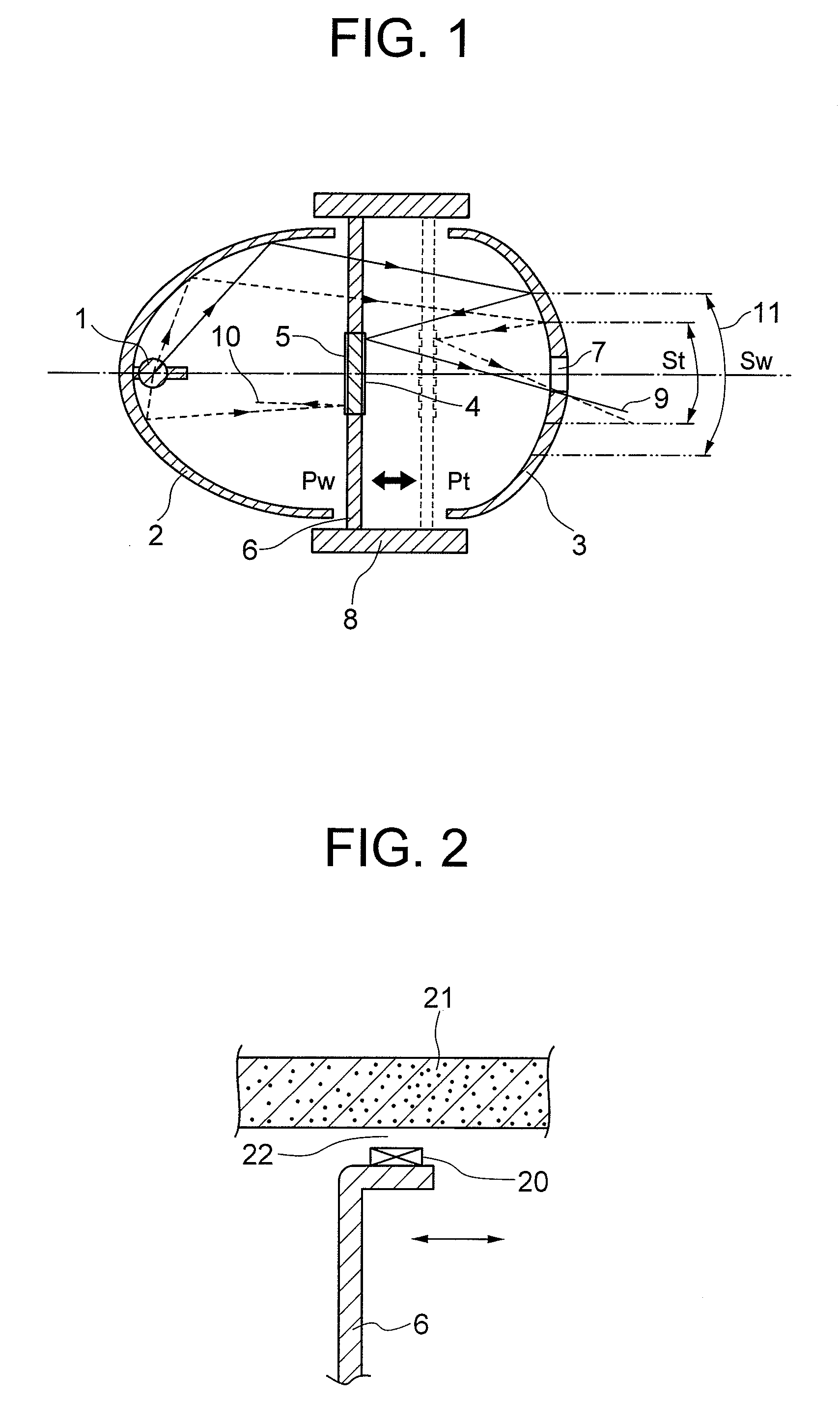
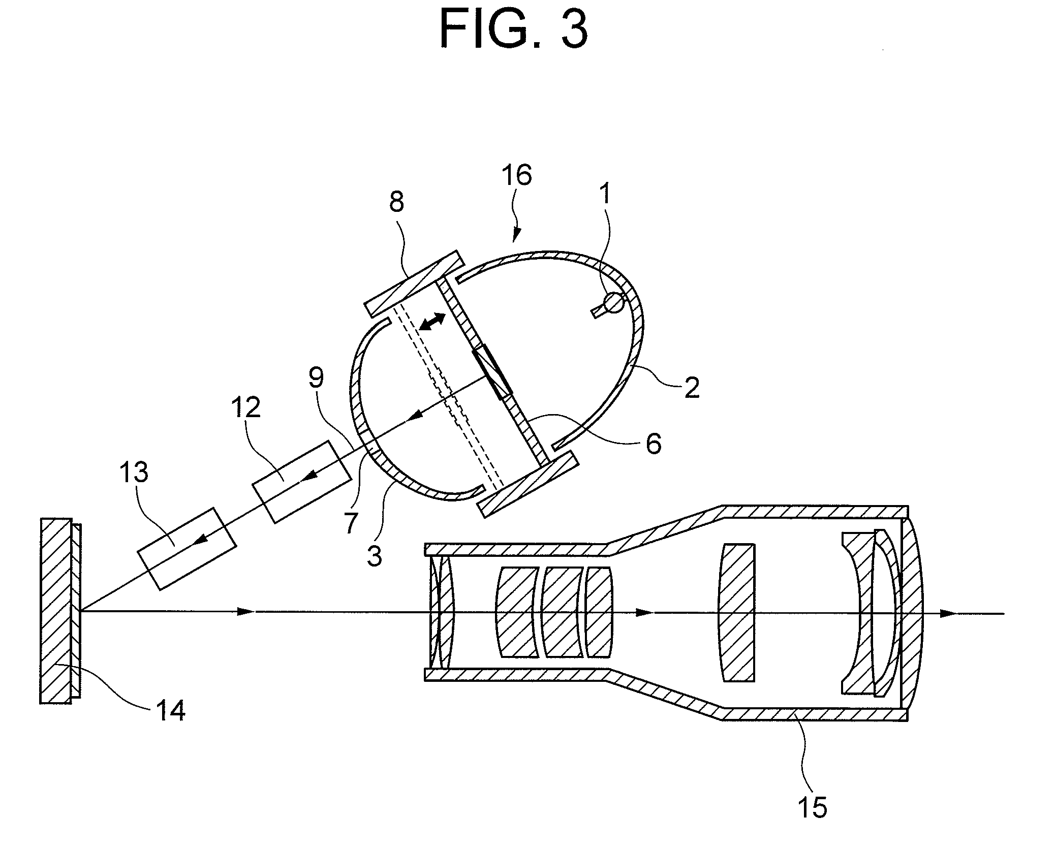
[0050]A first embodiment of an illuminating device and a image display device according to the present invention will be described with reference to FIGS. 1 to 7.

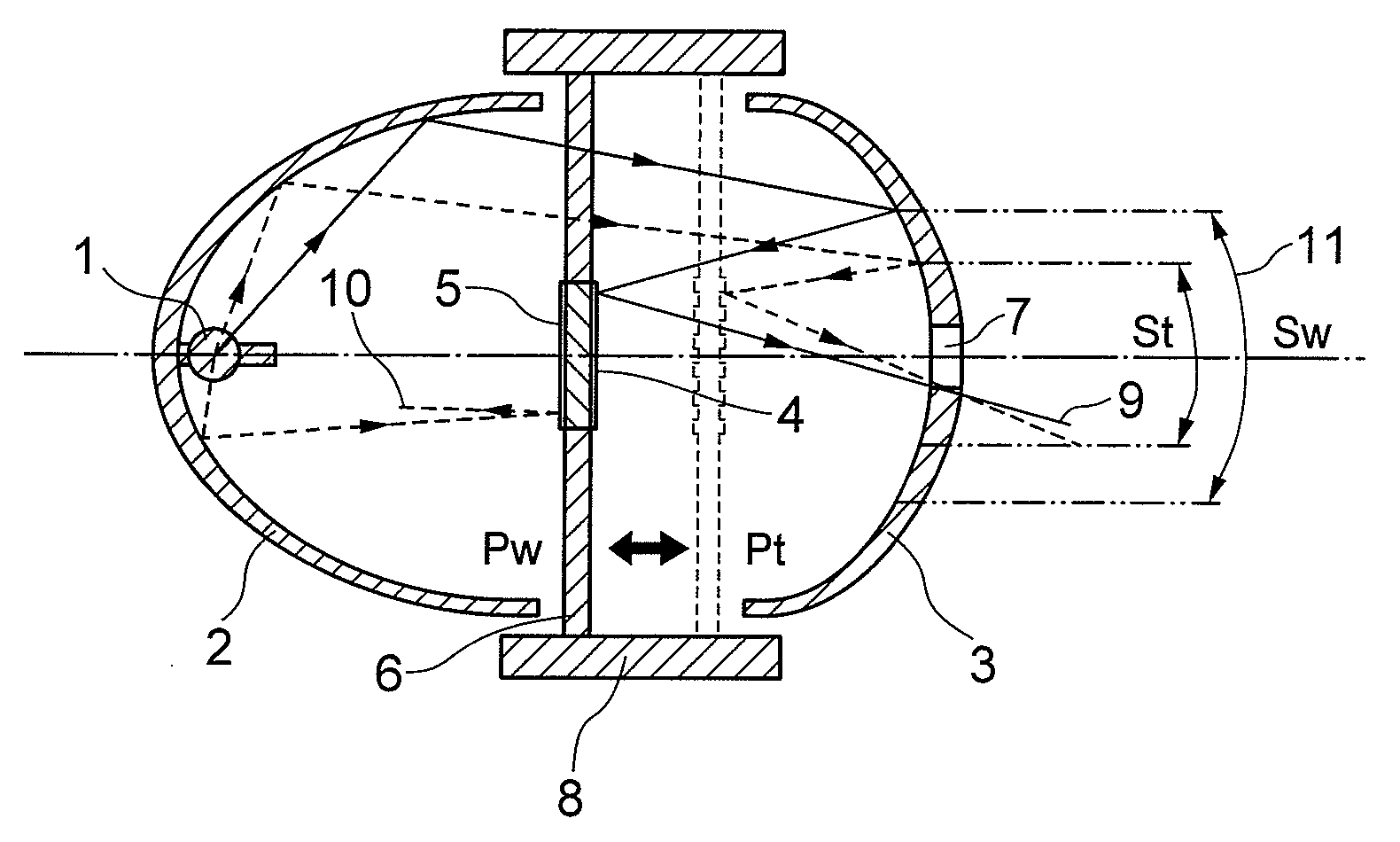
[0051]In FIG. 1, Reference Numeral 1 denotes a high-color-rendering point light source, such as a metal halide lamp, a high-pressure mercury lamp, a xenon lamp, or an LED, that is high-luminance and superior in the spectral characteristics. The light source 1 is disposed in the vicinity of a middle-bottom portion (on an optical center) of a first reflector 2 utilizing an elliptic mirror, a parabolic mirror, or the like, and a spherical-surface or aspherical-surface second reflector 3, having a concave contour, which is designed so as to reflect and condense light beams is disposed in front of the first reflector 2. An aperture 7 is formed in the vicinity of a middle-bottom portion (on an optical axis) of the second reflector 3.

[0052]As shown in FIG. 1, the first reflector 2 and the second reflector 3 are designed so that di...


PUM

PropertyMeasurementUnit
light reflectanceaaaaaaaaaa
frequencyaaaaaaaaaa
surface roughnessaaaaaaaaaa

Abstract

An illuminating device according to the present invention comprises a first reflector for irradiating forward light beams from a light source, a second reflector that has an aperture and is disposed in front of the first reflector so as to reflect toward the light source the light beams from the first reflector to condense the light beams, a third reflector disposed so as to make the light beams condensed by the second reflector exit through the aperture, and a reflector moving means that moves the second reflector or the third reflector along an optical axis.

Description

CLAIM OF PRIORITY[0001]The present invention claims priority from Japanese application JP2006-154812 filed on Jun. 2, 2006, the content of which is hereby incorporated by reference into this application.BACKGROUND OF THE INVENTION[0002]The present invention relates to an illuminating device and a projected image display device using the same. JP-A-2002-23266 discloses an art in which an aperture is inserted in an optical path of a projection display device so as to adjust a quantity of light.[0003]In addition, an art has been proposed in which, as a means for increasing contrast ratio of a display image of a projection display device, thereby enhancing the brightness and darkness of the display image and increasing hue depth at intermediate scale, an aperture is mechanically and rapidly inserted in the light path, with a time cycle in synchronization with an image frame, so as to dynamically adjust a quantity of light.[0004]Alternatively, an art has been proposed in which an illumin...

Claims


Application Information

Patent Timeline
Patent Type & Authority Applications(United States)
IPC IPC(8): F21V7/00F21Y101/00
CPCB60Q1/085F21S48/1388F21S48/1394H04N9/315F21V7/0008F21V7/22G02B17/0631F21S48/1757F21S41/24F21S41/321F21S41/365F21S41/37F21S41/675F21V7/28
Inventor GOTO, TAKAHIKOOHKURA, TAKAHIRO
Owner KYOCERA OPTEC
Why Eureka
Try Eureka