Method and system for adjusting the sensitivity of optical sensors

a technology of optical sensors and sensitivity adjustment, applied in the field of optical sensors, can solve the problems of limited resolution of optical sensors using an otdr, different amounts of time to return, and limited sensitivity of such optical sensors

Inactive Publication Date: 2007-12-06
HONEYWELL INT INC
View PDF2 Cites 12 Cited by
  • Summary
  • Abstract
  • Description
  • Claims
  • Application Information

AI Technical Summary

Problems solved by technology

However, depending on the particular type of optical sensor, the measurement being made may not be of the total amount of time it takes for the light to travel the given path, but rather of the time difference it takes different portions of the light to travel the optical path.
The result is that the two portions of light travel different optical path lengths, and thus require different amounts of time to return to the OTDR.
The resolution, and thus the sensitivity, of such optical sensors is limited by the sensitivity of the particular device or process being used to detect the returning light and meas

Method used


Image

  • Method and system for adjusting the sensitivity of optical sensors
  • Method and system for adjusting the sensitivity of optical sensors
  • Method and system for adjusting the sensitivity of optical sensors

Examples


Embodiment Construction

[0015] The following detailed description is merely exemplary in nature and is not intended to limit the invention or the application and uses of the invention. Furthermore, there is no intention to be bound by any expressed or implied theory presented in the preceding technical field, background, brief summary or the following detailed description. It should also be noted that FIGS. 1-3 are merely illustrative and may not be drawn to scale.

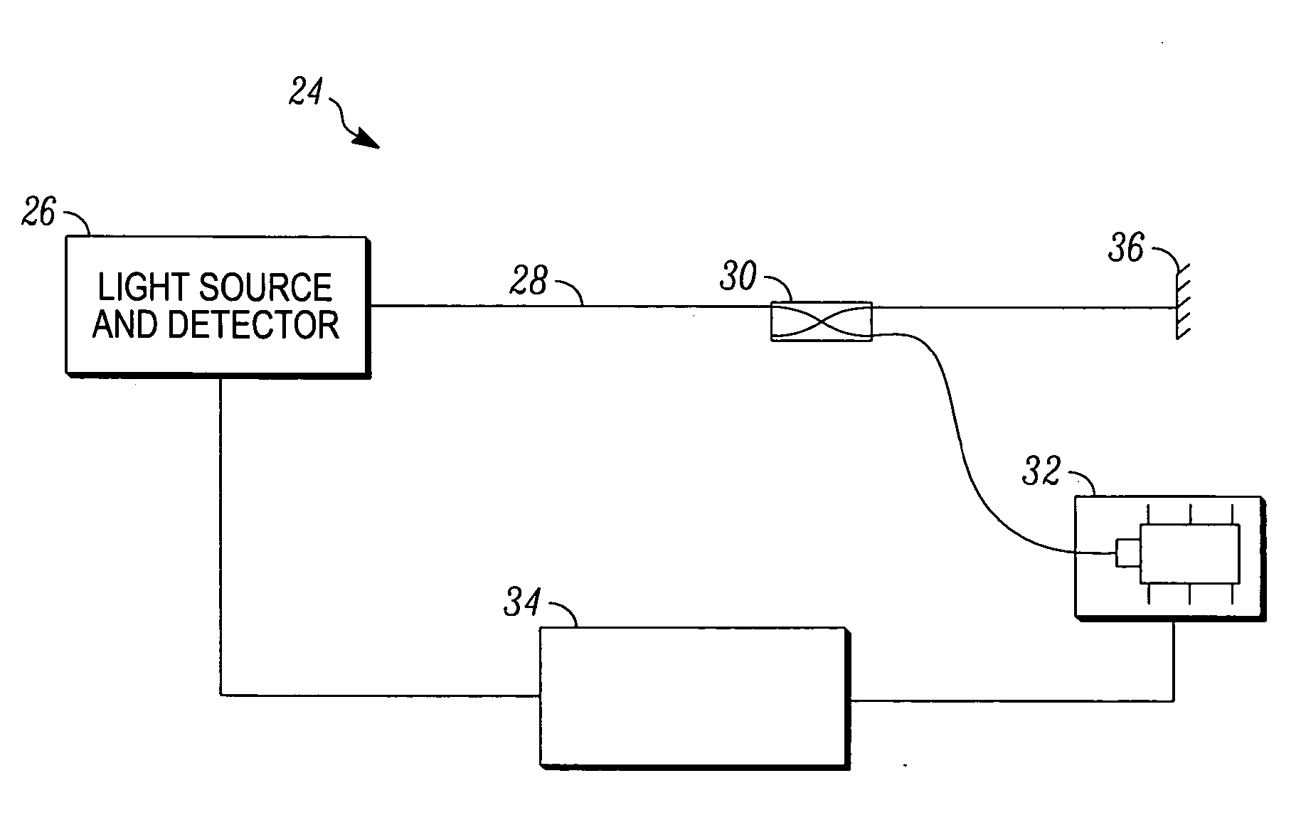
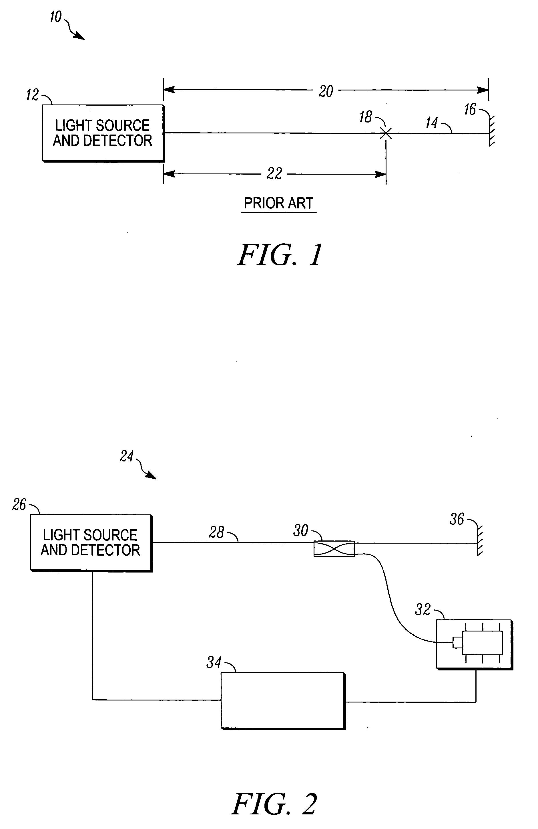
[0016]FIG. 1 illustrates a fiber optic sensor 10. The fiber optic sensor 10 includes a light source and detector 12 and an optical fiber 14 coupled to an output of the light source and detector 12. The optical fiber 14 includes a reflector 16 at an end thereof opposing the light source and detector 12 and a beam splitting feature 18 at a middle portion thereof. The reflector 16 may be any one of numerous types of reflective devices such as a mirror, a right-angle cleaved end, or simply an end cap connected to the optical fiber 14. The beam split...


PUM


Abstract

A method and a system for adjusting the sensitivity of an optical sensor are provided. A first beam of light in an optical fiber is separated into first and second portions propagating therethrough at a first speed. A second beam of light is directed into the optical fiber to interact with the first beam of light such that the first and second portions propagate through the optical fiber at a second speed. The propagation speed in turn influences the sensitivity of the optical sensor.

Description

[0001] This application claims the benefit of U.S. Provisional Application No. 60 / 811,455, filed Jun. 5, 2006.TECHNICAL FIELD [0002] The present invention generally relates to optical sensors, and more particularly relates to a method and system for adjusting the sensitivity of fiber optic sensors. BACKGROUND [0003] In recent years optical sensors have become widely used in various technologies to make many different sorts of measurements. Many optical sensors, such as strain sensors and fiber optic gyroscopes, operate by making “time of flight measurements.” That is, such optical sensors measure the amount of time it takes for light to travel a particular optical path length, such as down the length of an optical fiber or around a coil of optical fiber. However, depending on the particular type of optical sensor, the measurement being made may not be of the total amount of time it takes for the light to travel the given path, but rather of the time difference it takes different por...

Claims


Application Information

Patent Timeline
IPC IPC(8): G02B6/00
CPCG01K11/32G01M11/3109G01D5/35364G01D5/35348G01M11/319
Inventor SANDERS, STEVEN J.
Owner HONEYWELL INT INC
Why Eureka
Try Eureka