Liquid storage apparatus and image forming apparatus

a technology of liquid storage apparatus and image forming apparatus, which is applied in the direction of positive displacement liquid engine, fluid pressure control, instruments, etc., can solve the problems of print quality decline, and achieve the effect of preventing the occurrence of variations in ejection performance and preventing the decline of print quality

Inactive Publication Date: 2007-12-06
FUJIFILM CORP
View PDF22 Cites 17 Cited by
  • Summary
  • Abstract
  • Description
  • Claims
  • Application Information

AI Technical Summary

Benefits of technology

[0027]In this aspect of the invention, it is possible to supply liquid stably from the liquid storage apparatus to the liquid ejection head, and therefore it is possible to prevent the occurrence of variations in the ejection performance of the liquid ejection head and to thereby prevent decline in the print quality.
[0028]According to the present invention, it is possible to adjust the pressure of the stored liquid or the height of the liquid surface appropriately, and hence liquid can be supplied in a stable fashion.

Problems solved by technology

On the other hand, in the case of an ink tank having a large capacity, since the force generated by the elastic deformation increases, then the negative pressure exceeds the appropriate limit and the ejection state of the ink ejection head is thus affected, leading to a decline in print quality.

Method used


Image

  • Liquid storage apparatus and image forming apparatus
  • Liquid storage apparatus and image forming apparatus
  • Liquid storage apparatus and image forming apparatus

Examples


first embodiment

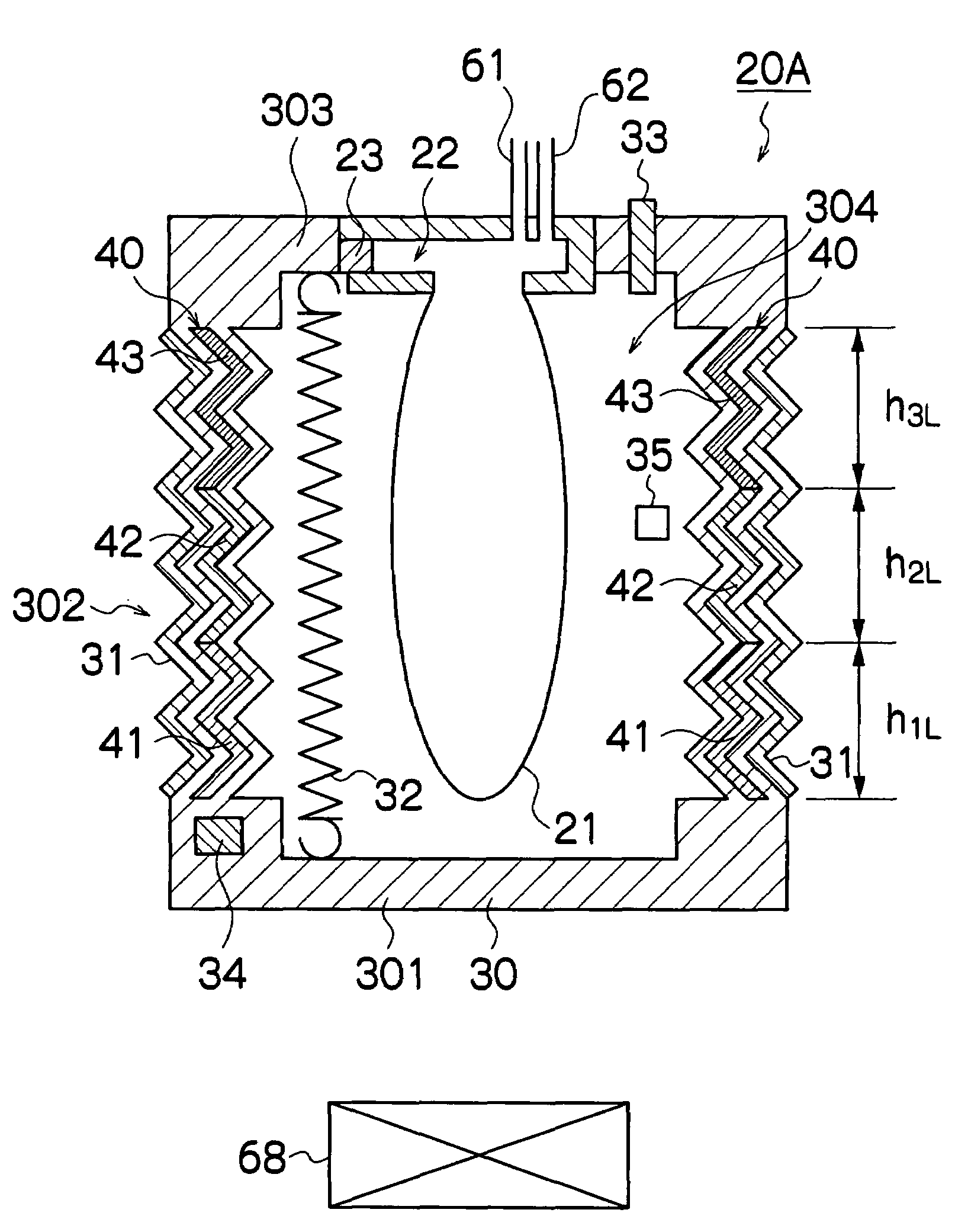
[0062]FIG. 3 is a cross-sectional diagram showing the internal structure of a sub tank 20A forming the liquid storage apparatus according to a first embodiment of the present invention.

[0063]As shown in FIG. 3, the sub tank 20A includes an external container 30 which is configured to accommodate a liquid storage chamber 21 constituted by a flexible bag member and which has concertina shaped side walls 302. In other words, a hermetically sealed space 304 is formed inside the external container 30 (more specifically, as shown in FIG. 3, a space is defined by the inner surface of the external container 30 and the outer surface of the liquid storage chamber 21). The liquid storage chamber 21 for storing the ink is accommodated in the hermetically sealed space 304 inside the external container 30. Since the liquid storage chamber 21 has flexibility, then the pressure inside the liquid storage chamber 21 is kept at substantially the same pressure as the pressure in the hermetically sealed...

second embodiment

[0099]FIG. 8 is a cross-sectional diagram showing the internal structure of a sub tank 20B forming the liquid storage apparatus according to a second embodiment of the present invention. The same reference numerals are assigned to constituent elements which are the same as those of the sub tank 20A according to the first embodiment shown in FIG. 3, and the description of details already explained above is omitted here.

[0100]In FIG. 8, the shape memory member 400 provided in the side walls 302 of the external container 30 is a material that is uniform throughout from the upper end to the lower end. Hence, the transformation temperature and the shape recovery temperature are also uniform throughout the whole of the shape memory member 400.

[0101]Moreover, the external container heater 310 provided along the whole of the shape memory member 400 embedded in the side walls 302 of the external container 30, is constituted by electrical heating wires. The density of the electrical heating w...

third embodiment

[0105]FIG. 10 is a cross-sectional diagram showing the internal structure of a sub tank 20C forming the liquid storage apparatus according to a third embodiment of the present invention. The same reference numerals are assigned to constituent elements which are the same as those of the sub tank 20A of the first embodiment shown in FIG. 3, and the description of details already explained above is omitted here.

[0106]In FIG. 10, a heater 25 for heating the ink in the liquid storage chamber 21 (hereinafter, referred to as “ink heater”) is provided inside the liquid storage chamber 21. The ink heater 25 used in the present embodiment is rod shaped. The upper portion of the ink heater 25 is supported by the ceiling plate 303 of the external container 30, while the central portion and the lower portion thereof are disposed inside the liquid storage chamber 21 so as to come in contact with the ink inside the liquid storage chamber 21.

[0107]To give a brief description, the sub tank 20C accor...


PUM


Abstract

The liquid storage apparatus includes: a liquid storage chamber which is constituted by a flexible bag member and stores liquid; an exterior container which has walls constituted by a shape memory member and has a hermetically sealed space in which the liquid storage chamber is disposed, the shape memory member extending and contracting freely at temperatures not greater than a transformation temperature and recovering a memorized shape at temperatures not less than a shape recovery temperature; a forcing member which applies a contraction force to the walls of the exterior container in a direction in which the walls contract; and a temperature adjuster which adjusts a temperature of the shape memory member directly or indirectly so as to control a ratio of a portion of the shape memory member having temperatures not greater than the transformation temperature and deformed to a contracted shape by the contraction force of the forcing member and a ratio of a portion of the shape memory member having temperatures not less than the shape recovery temperature and recovering the memorized shape more extended than the contracted shape, so that a pressure in the liquid storage chamber is changed depending on a volume change of the exterior container due to deformation of the shape memory member.

Description

BACKGROUND OF THE INVENTION[0001]1. Field of the Invention[0002]The present invention relates to a liquid storage apparatus for storing liquid, and to an image forming apparatus including this liquid storage apparatus.[0003]2. Description of the Related Art[0004]Various types of liquid storage apparatuses for storing ink to be supplied to an ink ejection head are known. An ink ejection head ejects ink supplied from the liquid storage apparatus toward an ejection receiving medium, such as paper, and forms images on the ejection receiving medium.[0005]Japanese Patent Application Publication No. 2004-230890 discloses an ink cartridge comprising: a housing which defines a first fluid tank; an air management system having an attachment to be supported by the housing; and an expansible bladder which defines a second fluid tank and which is supported by the attachment within the first fluid tank. The expansible bladder is configured to expand to thereby increase the second fluid tank from ...

Claims


Application Information

Patent Timeline
Patent Type & Authority Applications(United States)
IPC IPC(8): G03G21/20G03G9/00G05D23/00
CPCB41J2/175B41J2/17513B41J2/17553G05D16/2066B41J2/17566B41J2002/17516F03G7/065B41J2/17556
Inventor KATADA, MASAHITOTAKATSUKA, TSUTOMU
Owner FUJIFILM CORP
Why Eureka
Try Eureka