Fuel Cell System

a fuel cell and system technology, applied in the direction of fuel cell control, electric generators, doors/windows, etc., can solve the problems of fuel gas short supply, fuel gas insufficient supply, fuel depletion phenomenon, etc., and achieve the effect of quick control of output power

Active Publication Date: 2007-12-06
KYOCERA CORP
View PDF5 Cites 3 Cited by
  • Summary
  • Abstract
  • Description
  • Claims
  • Application Information

AI Technical Summary

Benefits of technology

[0006] It is, therefore, a principal object of the present invention to provide a novel and improved fuel cell system which is capable of sufficiently quickly controlling the output power and of properly controlling the flow rate of the fuel gas and the flow rate of the oxygen-containing gas in response to a variation in the load without permitting the occurrence of fuel depletion phenomenon.
[0007] Another object of the present invention is to provide a novel and improved fuel cell system which is capable of coping with the requirements very easily without requiring a great modification in the control system even when it is desired to change the load for which the fuel cell system is to be provided or when the fuel cell system is to be added to a single load.
[0008] Through their keen study, the present inventors have discovered the fact that the occurrence of fuel depletion phenomenon can be avoided even when the output power of the fuel cells is quickly controlled to meet a variation in the load if the flow rate of the fuel gas and the flow rate of the oxygen-containing gas are set based on an electric current of the fuel cells by selecting a fuel gas buffer amount specific to the fuel cells to be not smaller than a fuel gas amount that is needed within a maximum period of increase-needing time until the flow rate of the fuel gas is increased to a required amount when the amount of increase in the flow rate of the fuel gas is set to be a maximum and have, thus, accomplished the above principal object. The expression “fuel gas buffer specific to the fuel cells” appearing in this specification stands for the fuel gas amount present in the fuel cells (e.g., in the gas passages formed in the electrode support board) due to the constitution of the fuel cells themselves in the normal state. In particular, when the fuel cells are of the solid electrolyte type, the fuel gas buffer amount can be increased to a sufficient degree without involving any problem.

Problems solved by technology

Therefore, the flow rate of the fuel gas cannot be instantaneously increased despite of having received the increase instruction, and increases involving a time lag of several seconds.
Therefore, when the amount of output power must be increased at a large rate, the fuel gas becomes in short supply in the fuel cells giving rise to the occurrence of a so-called fuel depletion phenomenon.
If the fuel depletion phenomenon occurs, the electric power is not obtained as required and, besides, the fuel cells are deteriorated.
However, the following problems are involved in the conventional fuel cell systems which are designed to avoid the occurrence of the fuel depletion phenomenon as described above.
Namely, the rate of following up the variations in the load becomes relatively sluggish since the output power is increased in a delayed manner or the rate of increasing the output power is limited to be not larger than a predetermined value.
When the load varies vigorously, the electric power in many cases is generated without properly following the variation in the load, and the effective generation efficiency decreases considerably.

Method used


Image

  • Fuel Cell System
  • Fuel Cell System
  • Fuel Cell System

Examples


Embodiment Construction

[0017] A preferred embodiment of the fuel cell system constituted according to the present invention will be described below in further detail with reference to the accompanying drawings.

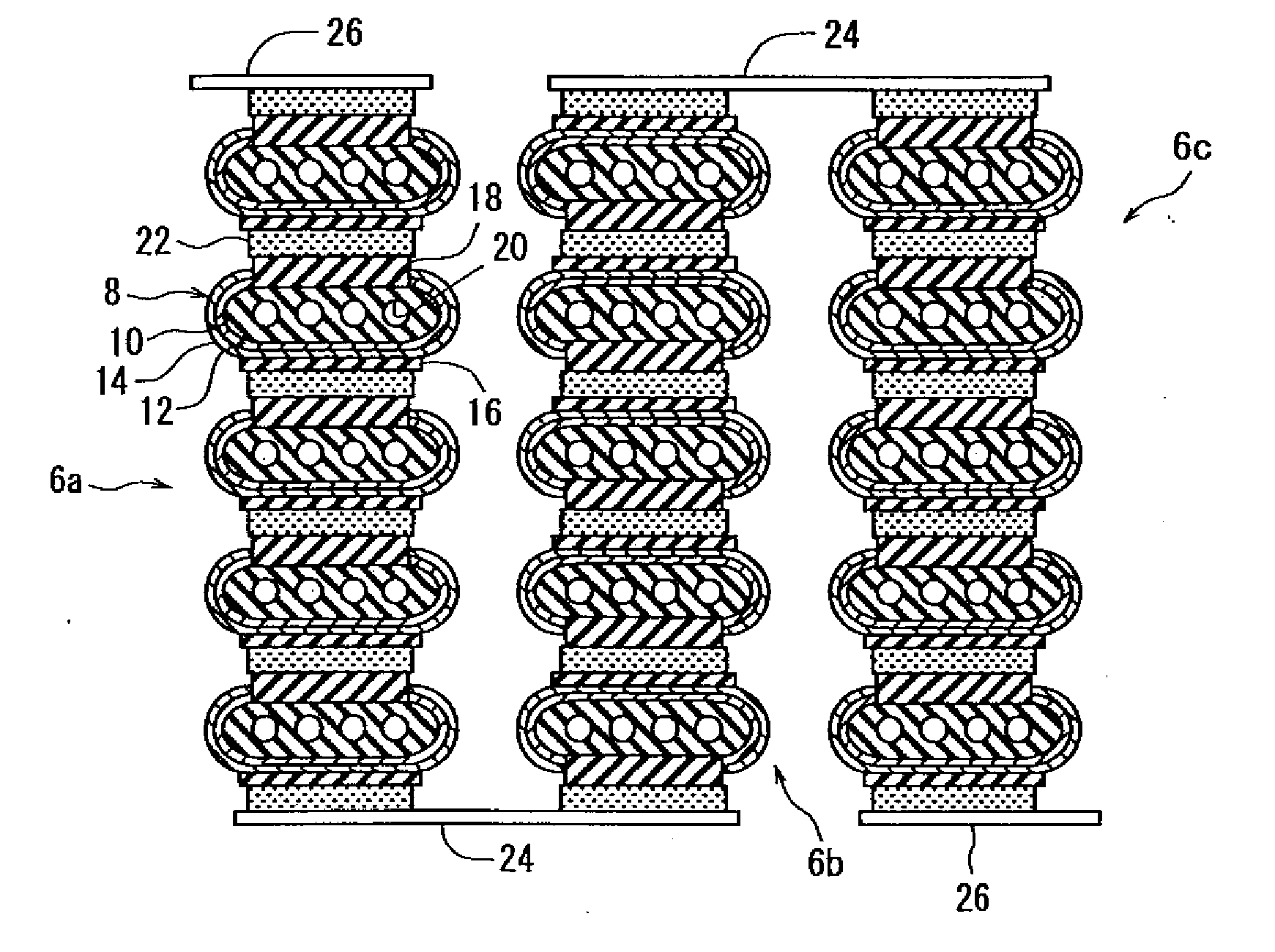
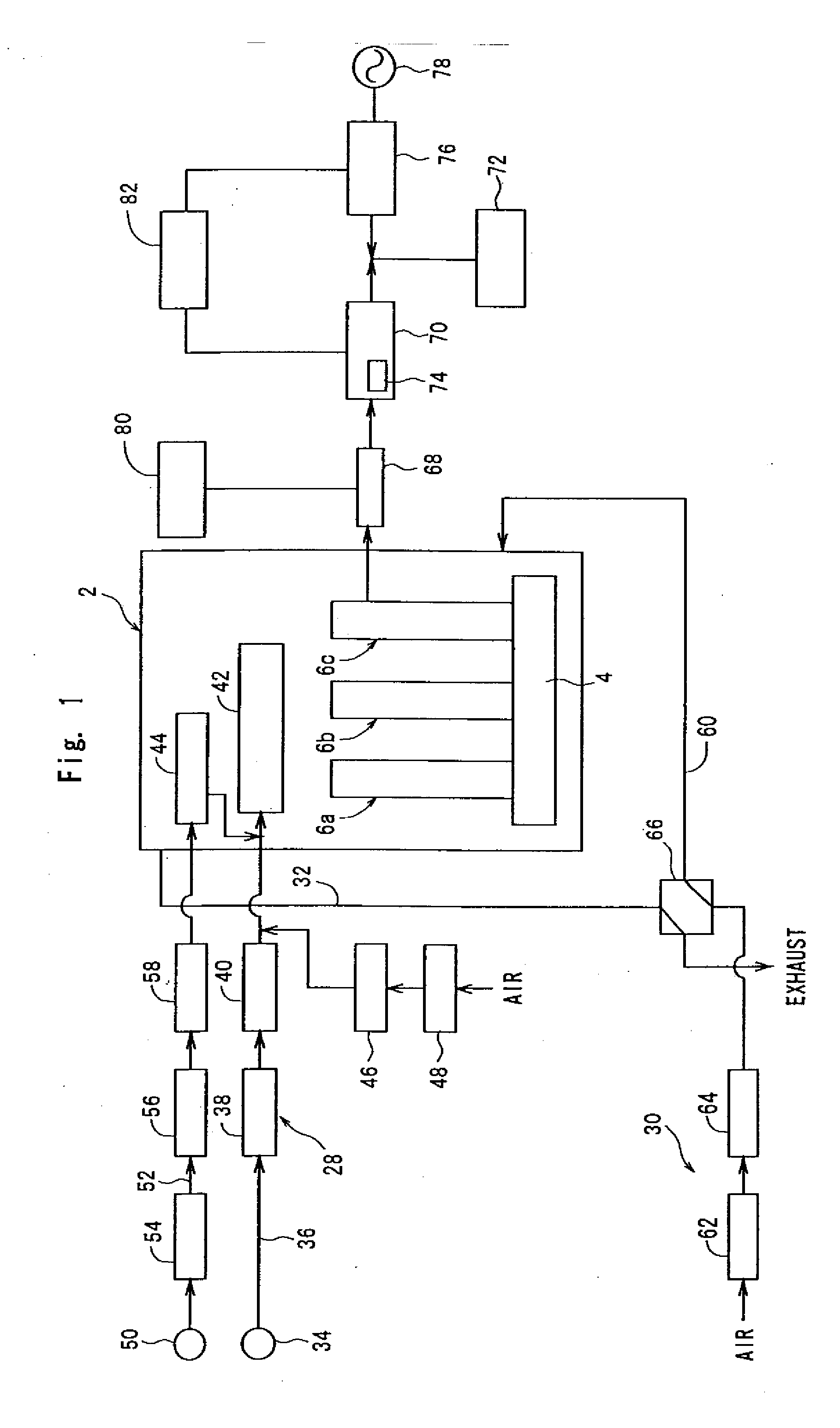
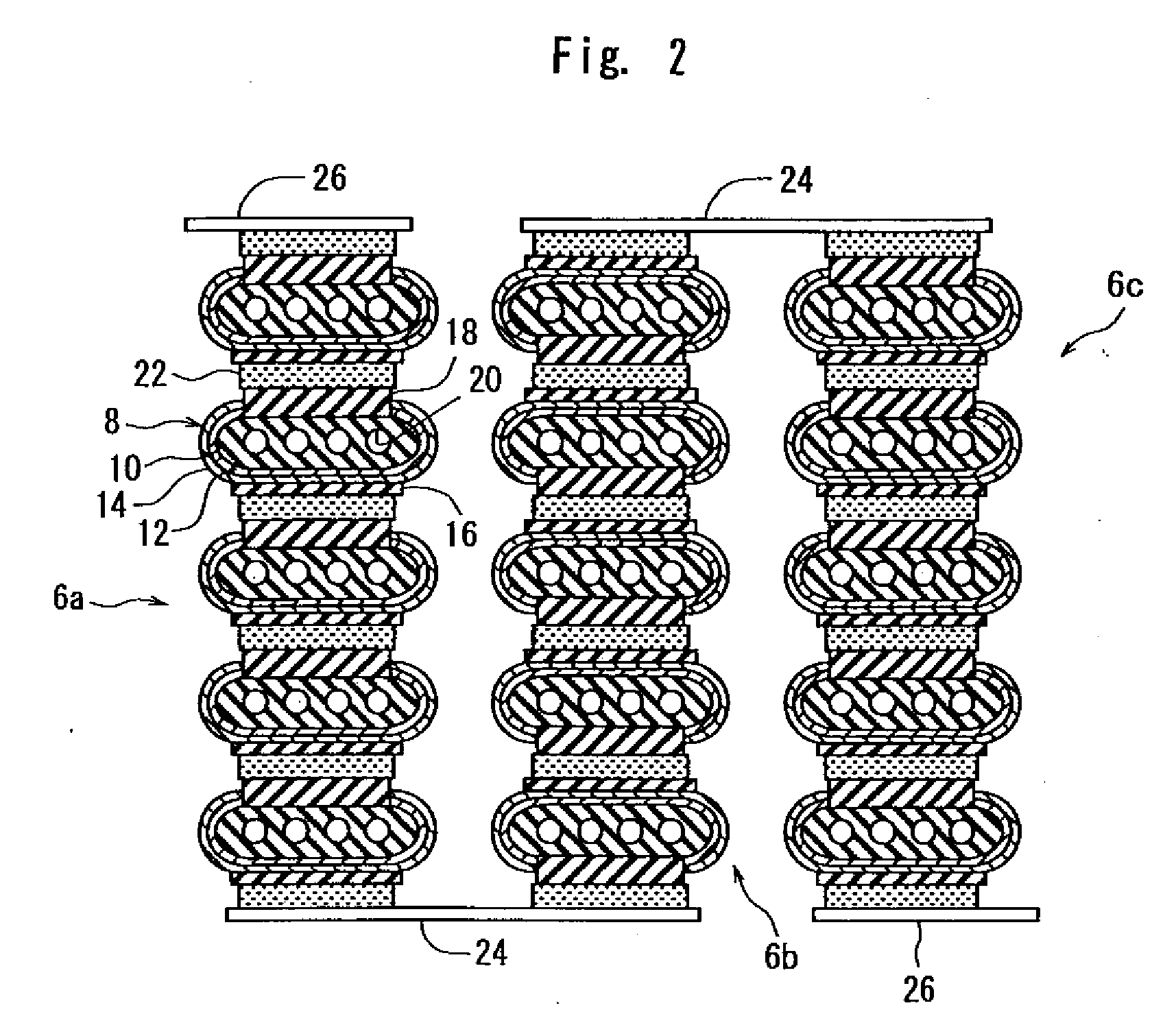
[0018]FIG. 1 simply illustrates the principal constituent elements of the fuel cell system constituted according to the present invention. The fuel cell system that is illustrated includes a generation chamber 2 which may be of a rectangular parallelepiped shape. It is desired that the generation chamber 2 is constituted by an outer frame made of a heat resisting metal plate and a heat insulating member arranged along the inner surfaces of the outer frame. A fuel gas tank 4 of the shape of a box is arranged in the lower part of the generation chamber 2. Fuel cell stacks 6a, 6b and 6c are arranged on the fuel gas tank 4. If described with reference to FIG. 1 as well as FIG. 2, the fuel cell stacks 6a, 6b and 6c are, respectively, constituted by a plurality of (five in the illustrated embodiment) fue...


PUM

PropertyMeasurementUnit
temperatureaaaaaaaaaa
flow rateaaaaaaaaaa

Abstract

A fuel cell system comprising a generation chamber, a plurality of fuel cells arranged in the generation chamber, fuel gas feeding means for feeding a fuel gas to the fuel cells, oxygen-containing gas feeding means for feeding an oxygen-containing gas to the fuel cells, power converter means for converting the DC output of the fuel cells into an alternating current, power control means for controlling the electric power output to the power converter means from the fuel cells, and generation control means for controlling the flow rate of the fuel gas fed to the fuel cells and the flow rate of the oxygen-containing gas fed to the fuel cells. A fuel gas buffer amount specific to the fuel cells is not smaller than a fuel gas amount that is needed within a maximum period of increase-needing time that is necessary until the flow rate of the fuel gas increases to a required amount when the amount of increase in the flow rate of the fuel gas is set to be a maximum. The generation control means sets the flow rate of the fuel gas and the flow rate of the oxygen-containing gas based on an electric current of the fuel cells.

Description

TECHNICAL FIELD [0001] The present invention relates to a fuel cell system equipped with power control means for controlling the amount of electric power produced by fuel cells and with generation control means for controlling the flow rate of a fuel gas and the flow rate of an oxygen-containing gas fed to the fuel cells. BACKGROUND ART [0002] As is widely known, a fuel cell system has been proposed and placed in practical use to generate electricity by putting a hydrogen-rich fuel gas and an oxygen-containing gas which may be the air to the electrode reaction. A representative example of the fuel cell system includes a generation chamber, a plurality of fuel cells arranged in the generation chamber, fuel gas feeding means for feeding a fuel gas to the fuel cells, oxygen-containing gas feeding means for feeding an oxygen-containing gas to the fuel cells, and power converter means for converting a DC output of the fuel cells into an alternating current. The power converter means feed...

Claims


Application Information

Patent Timeline
Patent Type & Authority Applications(United States)
IPC IPC(8): H01M8/04
CPCH01M8/04089H01M8/04223H01M8/04589H01M8/04753Y02E60/525H01M8/0606H01M8/243H01M2008/1293Y02E60/50H01M8/0488H01M8/2457H01M8/043
Inventor SHIGEHISA, TAKASHI
Owner KYOCERA CORP
Why Eureka
Try Eureka