Control circuit and tracking method of maximum power

a control circuit and maximum power technology, applied in the direction of dc-ac conversion without reversal, process and machine control, instruments, etc., can solve the problem of fairly high circuit cost of photovoltaic control circuit b>1/b>, and achieve the effect of lower circuit cost and simple structur

Inactive Publication Date: 2012-03-29
NAT CHENG KUNG UNIV
View PDF10 Cites 4 Cited by
  • Summary
  • Abstract
  • Description
  • Claims
  • Application Information

AI Technical Summary

Benefits of technology

[0032]As mentioned above, in the control circuit and tracking method of the maximum power of the present invention, the feed-forward unit generates a duty cycle reference signal according to the output signal of the power output module, and the feedback unit generates a feedback signal according to the driving signal output by the conversion unit. Besides, the control unit outputs a control signal to control the actuation of the switch element of the conversion unit to re-start the conversion unit, and cause the power

Problems solved by technology

Thus the circuit cost for the photovolta

Method used


Image

  • Control circuit and tracking method of maximum power
  • Control circuit and tracking method of maximum power
  • Control circuit and tracking method of maximum power

Examples


Embodiment Construction

[0044]The present invention will be apparent from the following detailed description, which proceeds with reference to the accompanying drawings, wherein the same references relate to the same elements.

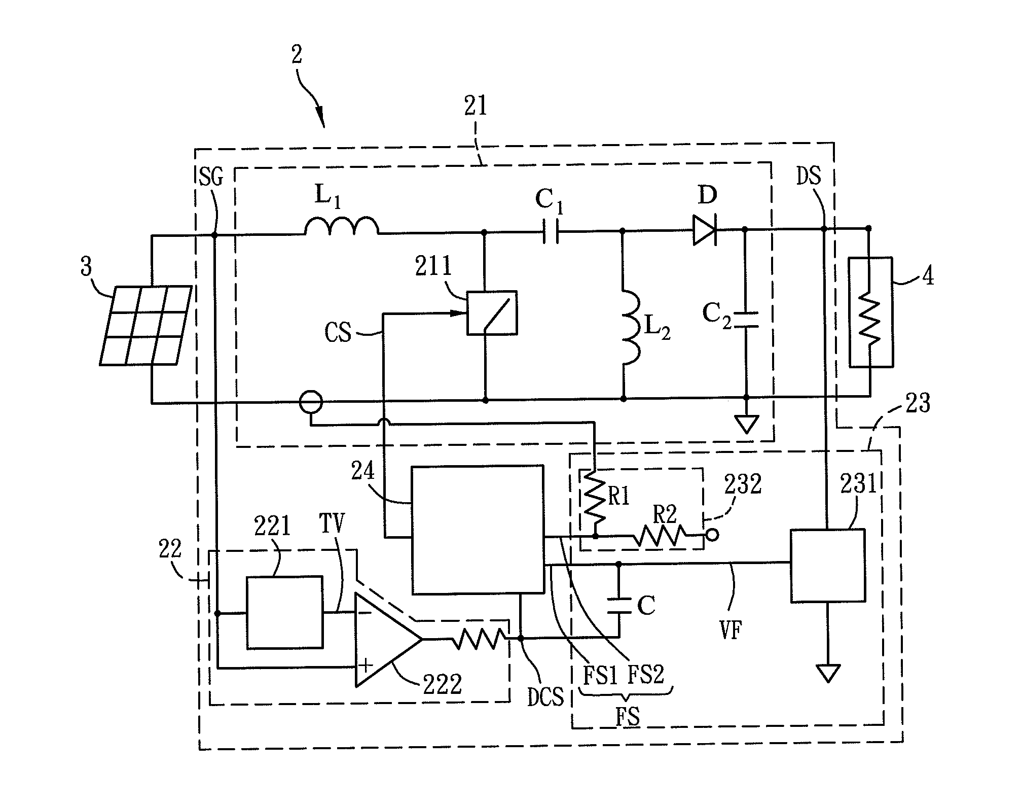
[0045]FIG. 2 is a block diagram of functions of a control circuit 2 according to a preferred embodiment of the present invention. Referring to FIG. 2, the control circuit 2 is used to control an output of a power output module 3 to supply a power to drive a load device 4. The power output module 3 includes a solar cell component or a solar cell module. The power output module 3 can be a solar cell, or the power output module 3 can be composed of a plurality of solar cells connected in parallel and / or in series. It is not limited in the present invention. Furthermore, the load device 4 can be a home appliance, a mobile phone, a computer, a GPS, a PDA, or other electronic products.

[0046]The control circuit 2 includes a conversion unit 21, a feed-forward unit 22, a feedback unit 23 and a...


PUM


Abstract

A control circuit controls a power output module and drives a load device. The control circuit includes a conversion unit, a feed-forward unit, a feedback unit and a control unit. The conversion unit generates a driving signal according to an output signal of the power output module for driving the load device. The feed-forward unit generates a duty cycle reference signal according to the output signal. The feedback unit generates a feedback signal according to the driving signal. The control unit outputs a control signal to control the conversion unit according to the duty cycle reference signal and feedback signal, thereby limiting the output power of the power output module within the maximum power region. A tracking method of the maximum power is also disclosed.

Description

CROSS REFERENCE TO RELATED APPLICATIONS[0001]This Non-provisional application claims priority under 35 U.S.C. §119(a) on Patent Application No(s). 099132446 filed in Taiwan, Republic of China on Sep. 24, 2010, the entire contents of which are hereby incorporated by reference.BACKGROUND OF THE INVENTION[0002]1. Field of Invention[0003]The present invention relates to a circuit and a tracking method, and in particular, to a control circuit and a tracking method of a maximum power.[0004]2. Related Art[0005]In the recent years, in the wake of heightened environmental consciousness and petrochemical energy such as petroleum and coal is running out, countries worldwide have started to realize an importance of developing new energy. Because sunlight is an energy, which is inexhaustible in supply and always available for use, we do not have to worry that it will run out and the problem with monopolization can also be avoided. Therefore, countries worldwide are devoted to developing applied ...

Claims


Application Information

Patent Timeline
IPC IPC(8): G05F1/46H02M7/44
CPCY10S323/906G05F1/67
Inventor LIN, RAY-LEECHOU, MING-CHING
Owner NAT CHENG KUNG UNIV
Why Eureka
Try Eureka