Photonic fabric display with controlled pattern, color, luminescence intensity, scattering intensity and light self-amplification

a technology of photonic fabric and controlled pattern, applied in the direction of floor carpet, optical light guide, light guide details, etc., can solve the problems of unsatisfactory luminescence intensity and scattering intensity of these displays

Active Publication Date: 2007-12-06
THE HONG KONG POLYTECHNIC UNIV
View PDF7 Cites 56 Cited by
  • Summary
  • Abstract
  • Description
  • Claims
  • Application Information

AI Technical Summary

Problems solved by technology
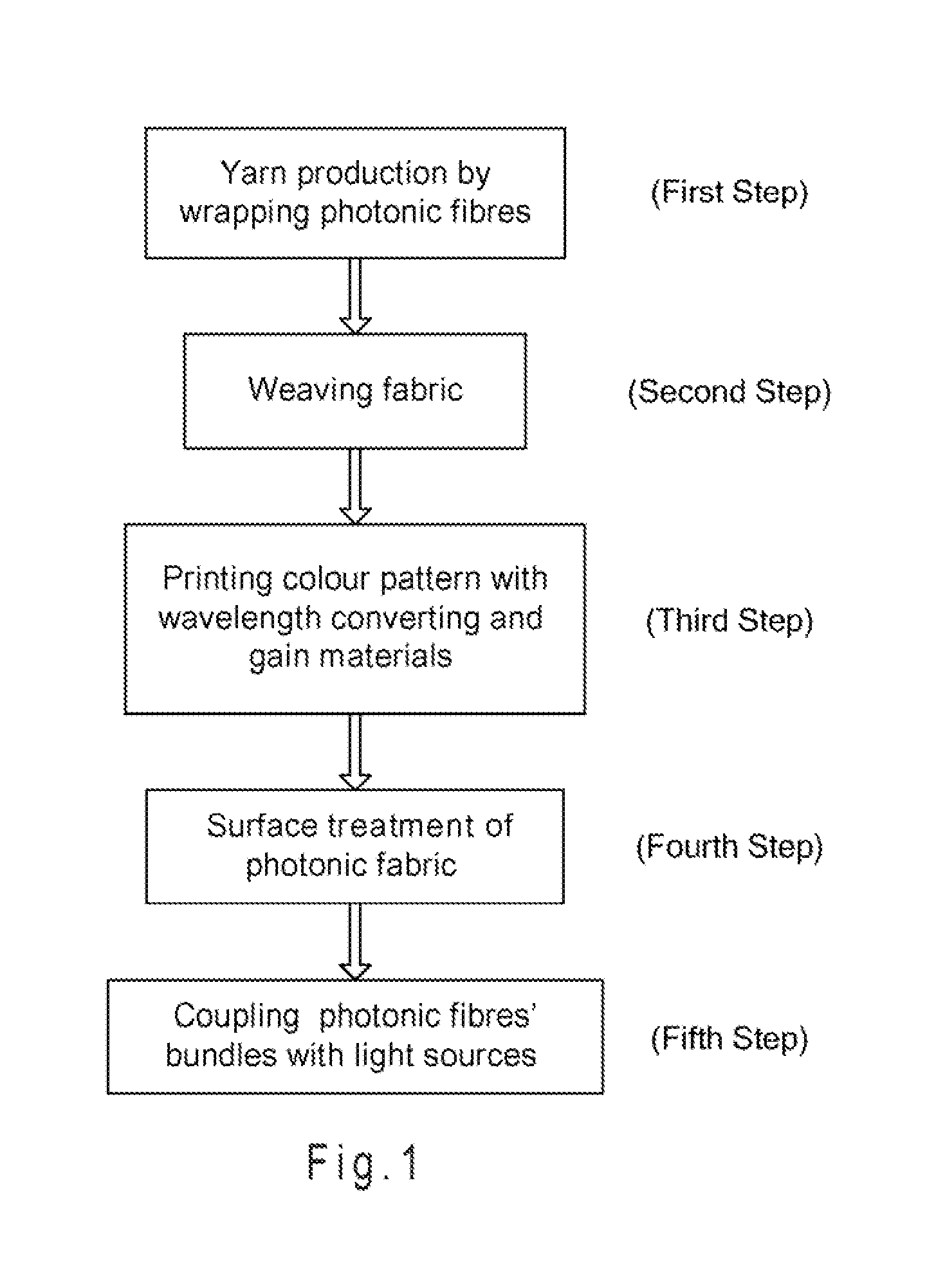
However, the luminescence intensity and scattering intensity of these displays are often unsatisfactory, highlighted with unattractive color patterns and under-performing light amplification.

Method used


Image

  • Photonic fabric display with controlled pattern, color, luminescence intensity, scattering intensity and light self-amplification
  • Photonic fabric display with controlled pattern, color, luminescence intensity, scattering intensity and light self-amplification
  • Photonic fabric display with controlled pattern, color, luminescence intensity, scattering intensity and light self-amplification

Examples


example 1

The Photonic Fabric Display as Used in Painting-Formatted Art Decor

[0044] The painting-formatted art decor made by a photonic fabric display is shown in FIG. 5, which depicts the Harbor View of Hong Kong. Electronic circuits were used to control the patterns, luminescent effects, and display mode.

example 2

The Photonic Fabric Display as Used in a Luminescent Costume

[0045] The luminescent costume for a ballerina made by a photonic fabric display is shown in FIG. 6. The costume had three layers of light and soft photonic fabric display, each layer having a different color, luminescence pattern and intensity. The fabric included polymeric photonic fibers blended with silk and polyester fibers, and fabricated to provide the desired light transmission and scattering properties, flexibility, drape and handle of textiles for the dancing costume. LEDs were coupled to the fabric, and power supplies were seamlessly integrated into the design of the costume.

example 3

Other Examples of the Photonic Fabric Display as Used in a Dining Room

[0046] The interior of a dining room furnished with photonic fabric displays is shown in FIG. 7. The wall fabric 22 and decorative picture 28, made from a number of light weight and thin double-sided luminescent photonic fabric displays, were hung on the inside walls of the dining room. These photonic fabric displays were capable of producing diffuse and soft light and were able to change the light color of the fabric displays in response to music that was being played.

[0047]FIG. 7 also shows a retractable droplight 20 made from photonic fabric displays hung under the roof. Through using different weaving style and gain materials, the droplight 20 produced more bright lights than those photonic fabric displays 22 hung on the wall. Through a glass floor board, a three-layered colored luminescent photonic fabric display 23 with tunable color and controllable light intensity was seen.

[0048] The double-sided lumine...


PUM

PropertyMeasurementUnit
refractive indexaaaaaaaaaa
diameteraaaaaaaaaa
diameteraaaaaaaaaa

Abstract

A method of making a photonic fabric display includes wrapping photonic fibers with a yarn, weaving the wrapped photonic fibers to form a fabric, printing a pattern on the fabric, surface treating the fabric, and coupling the photonic fibers with a light source to form a photonic fabric display.

Description

[0001] The present application claims priority to U.S. Non-provisional application Ser. No. 11 / 586,730, entitled “Photonic Fabric Display with Controlled Graphic Pattern, Color, Luminescence Intensity, and Light Self-Amplification,” which was filed on Oct. 26, 2006, the content of which is incorporated herein by reference. [0002] The present application also claims the benefit of U.S. Provisional Application No. 60 / 730,036, entitled “Photonic Fabric With Controlled Pattern, Color, Luminescence Intensity, Scattering Intensity, and Light Self-Amplification”, filed Oct. 26, 2005, the content of which is incorporated herein by reference.BACKGROUND [0003] Traditional illumination displays use optical fibers in a panel, where the surface of the optical fibers may be disrupted at desired locations to enable light to emit laterally, forming an intended graphic pattern or image. However, the luminescence intensity and scattering intensity of these displays are often unsatisfactory, highlight...

Claims


Application Information

Patent Timeline
Patent Type & Authority Applications(United States)
IPC IPC(8): D02G3/00A47G35/00D06C23/00
CPCA47G9/0284Y10T428/2915A47G27/0243A47H21/00A47H23/00B44F1/00D02G3/441D03D15/00D03D15/0027D03D15/0033D03D15/0077D10B2101/20D10B2201/02D10B2201/04D10B2211/02D10B2211/04D10B2321/121D10B2401/20D10B2501/00D10B2503/04D10B2503/06D10B2505/08D10B2505/18G02B6/001A47G2009/005F21V2200/15A47G11/003D03D15/49D03D15/54D03D15/47D03D15/547D03D15/292D03D15/283
Inventor TAO, XIAOMINGCHENG, XIAOYINYU, JIANMINGLIU, LIJIEWONG, WANG-WAHTAM, WING-KWONG
Owner THE HONG KONG POLYTECHNIC UNIV
Why Eureka
Try Eureka