Catheter with Pressure Sensor and Guidance System

a technology of pressure sensor and catheter tip, applied in the field of catheters, can solve the problems of difficulty in visualizing the position of the catheter tip, difficulty in identifying patients, and skilled clinicians receiving significant accumulated doses from multiple procedures

Inactive Publication Date: 2007-12-06
PHYSICAL LOGIC
View PDF3 Cites 55 Cited by
  • Summary
  • Abstract
  • Description
  • Claims
  • Application Information

AI Technical Summary

Benefits of technology

[0011]The above and other aspects of the invention help the physician avoid damage during vascular and other catheterization procedures as well as provide an alternative and complimentary means for detecting obstructions and blockages to radiography.

Problems solved by technology

As the contrast agent diffuses into capillaries, it again becomes difficult to visualize the position of the catheter tip.
However, difficulties arise as the catheter technology has improved to where it is possible to probe smaller and smaller conduits or channels.
Although the patient receives more X-radiation during a single procedure, the skilled clinician can receive significant accumulated dose from multiple procedures.

Method used


Image

  • Catheter with Pressure Sensor and Guidance System
  • Catheter with Pressure Sensor and Guidance System
  • Catheter with Pressure Sensor and Guidance System

Examples


Embodiment Construction

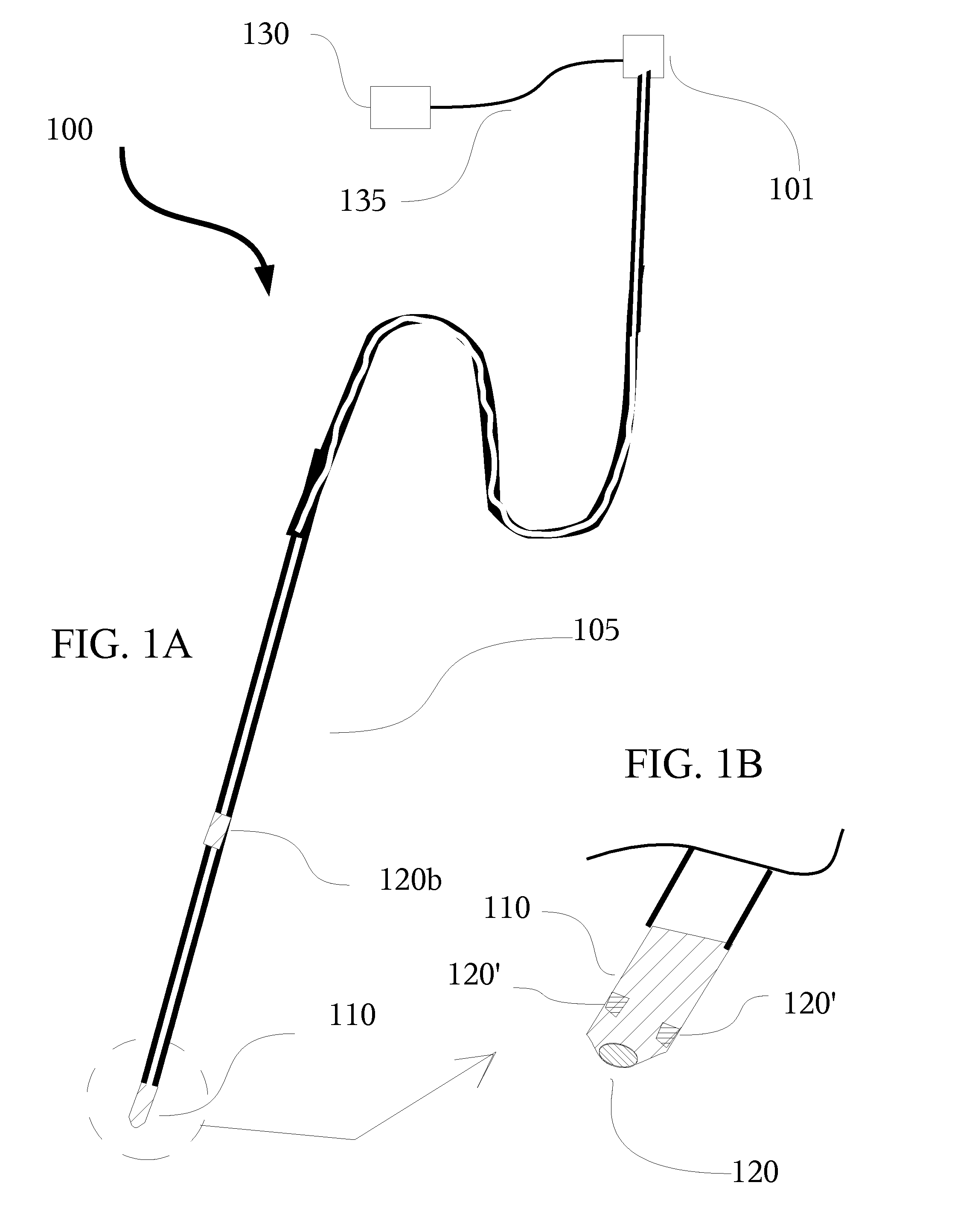
[0022]Referring to FIGS. 1 through 4 wherein like reference numerals refer to like components in the various views, there is illustrated therein a new and improved catheter with pressure sensor and guidance system, generally denominated 100 herein.

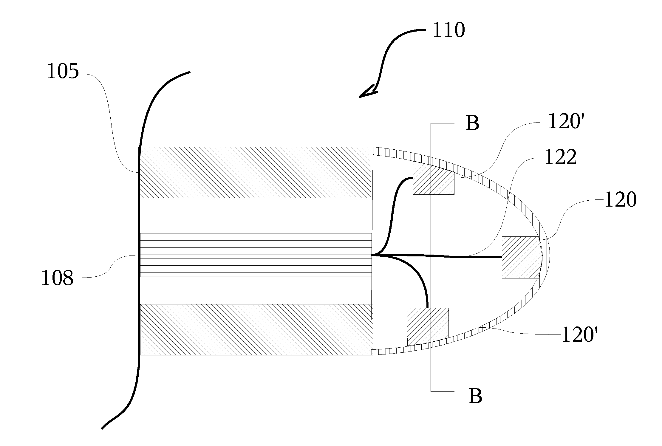
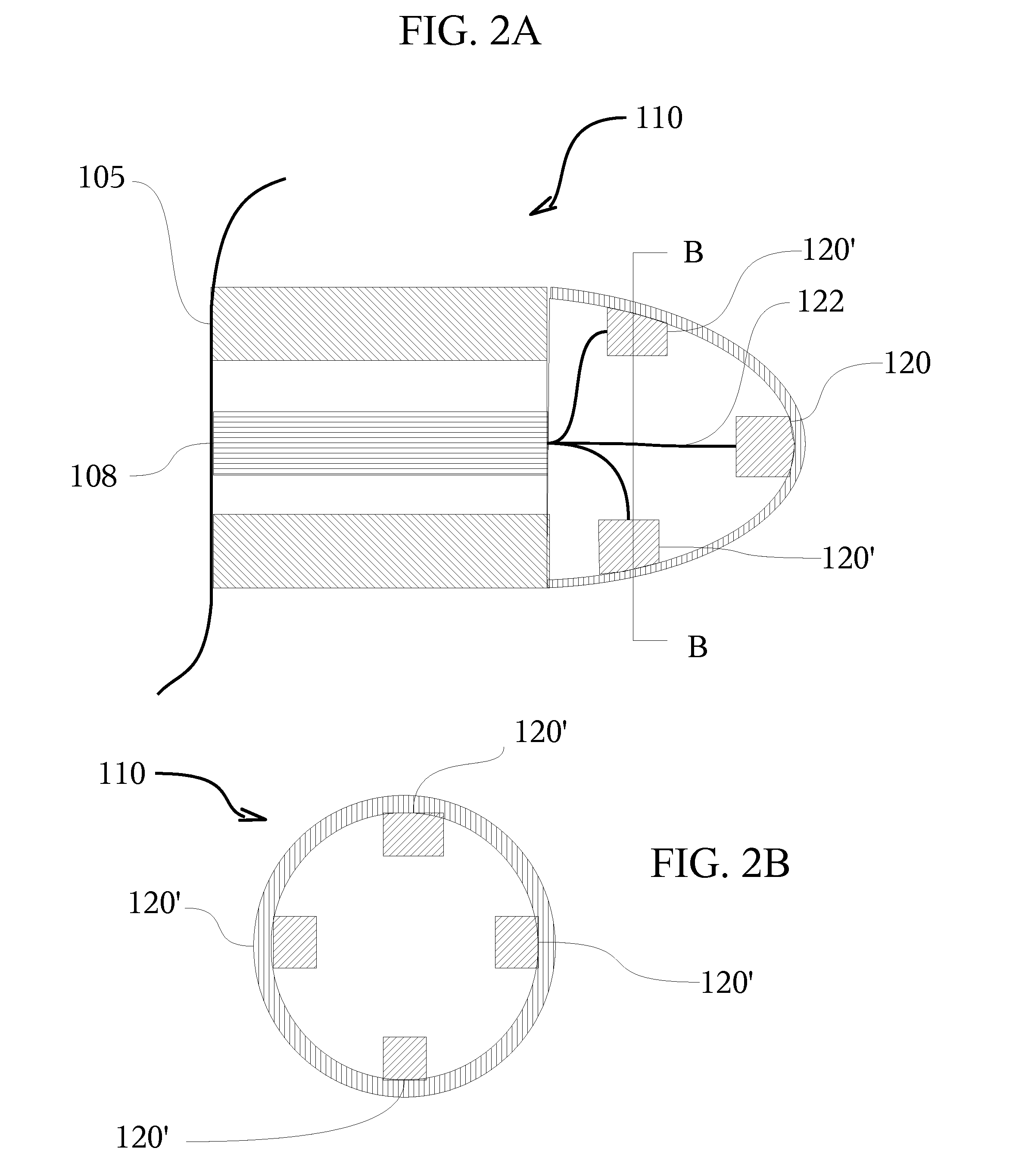
[0023]FIG. 1A illustrates such a catheter device 100 that comprises an elongated tube 105 that is at least partially flexible, and in particular most flexible wherein it terminates at a tip 110. A plurality of pressure sensors 120′ are distributed about the tip 110, one 120 being preferably at the apex of tip 110 as shown in the enlarged partial view in FIG. 1B. Additional sensors, preferably pressure sensors such as 120b, may be disturbed elsewhere along the elongated tube 105 distal from the tip 110 and closer to the conventional control means 101. The elongated tube 105 is at least partially flexible and preferably hollow, having an inner tubular cavity 103 (shown in FIG. 2A) The inner tubular cavity 103 may be used to deliver special p...


PUM


Abstract

A catheter terminates at a tip that includes an array of pressure sensors. The sensors are responsive to detect and alert the user to variations of pressure that indicate the tip is either encountering an obstruction or constriction of smaller diameter than the catheter, as well as to guide the catheter through the conduit into which it is being inserted.

Description

CROSS REFERENCE TO RELATED APPLICATIONS[0001]The present application claims priority to the U.S. Provisional Patent Application filed on Jun. 5, 2006, titled “Catheter with Pressure Sensor and Guidance System” and having Ser. No. 60 / 803,909, which is incorporated herein by reference.BACKGROUND OF INVENTION[0002]The present invention relates to catheters used in invasive medical procedures, and in particular to catheters with a capability to measure pressure.[0003]Catheters are extensively used in medical procedures to probe or open restricted vascular structures or other bodily conduits, in for example the delivery of contrast dyes for radiographic procedures, balloon angioplasty to open coronary or other arteries, delivery of stents, insertion of heart monitors and ECD leads as well as numerous other procedures on humans and other living creatures.[0004]In such catheterization procedures, it is essential that the physician visualize the location of the catheter in the body with res...

Claims


Application Information

Patent Timeline
Patent Type & Authority Applications(United States)
IPC IPC(8): A61B5/04A61B5/103
CPCA61B5/0215A61M25/008A61M2025/0166A61M2025/0002A61M25/0082
Inventor OFEK, ERANZIPES, DOUGLAS P.
Owner PHYSICAL LOGIC
Why Eureka
Try Eureka