
Guidewire formed with composite construction and method for making the same

Inactive Publication Date: 2007-12-06
CONCERT MEDICAL
View PDF10 Cites 12 Cited by
  • Summary
  • Abstract
  • Description
  • Claims
  • Application Information

AI Technical Summary

Benefits of technology

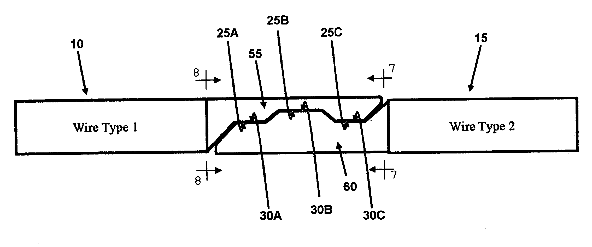
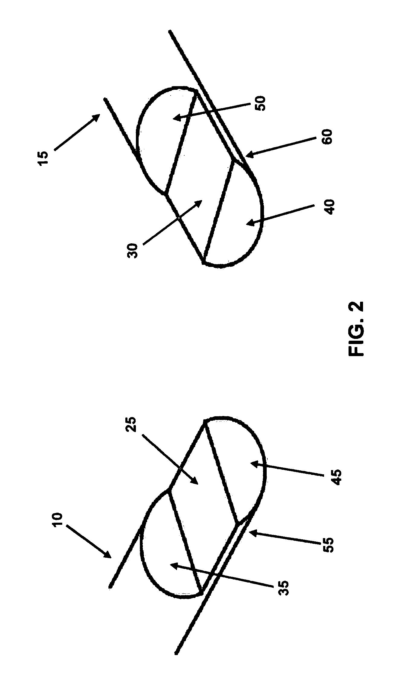
[0018] The present invention provides a means for joining together two different wire segments at a joint that provides improved (i) tensile strength, (ii) torque strength, (iii) bending moment performance, and (iv) failure mode characteristics, among other things, and which is suitable for medical applications. More particularly, using advanced grinding technology or other suitable manufacturing techniques, complementary flat planar bonding faces, suitable for overlapping bonding, are created at the ends of the two wire segments which are to be joined. The complementary flat planar bonding faces are of sufficient surface area as to provide the required tensile strength and torque strength for the guidewire.

Problems solved by technology

This joint can be problematic, inasmuch as it is imperative that the joint not undermine the integrity of the guidewire.

Method used


Image

  • Guidewire formed with composite construction and method for making the same
  • Guidewire formed with composite construction and method for making the same
  • Guidewire formed with composite construction and method for making the same

Examples


Embodiment Construction

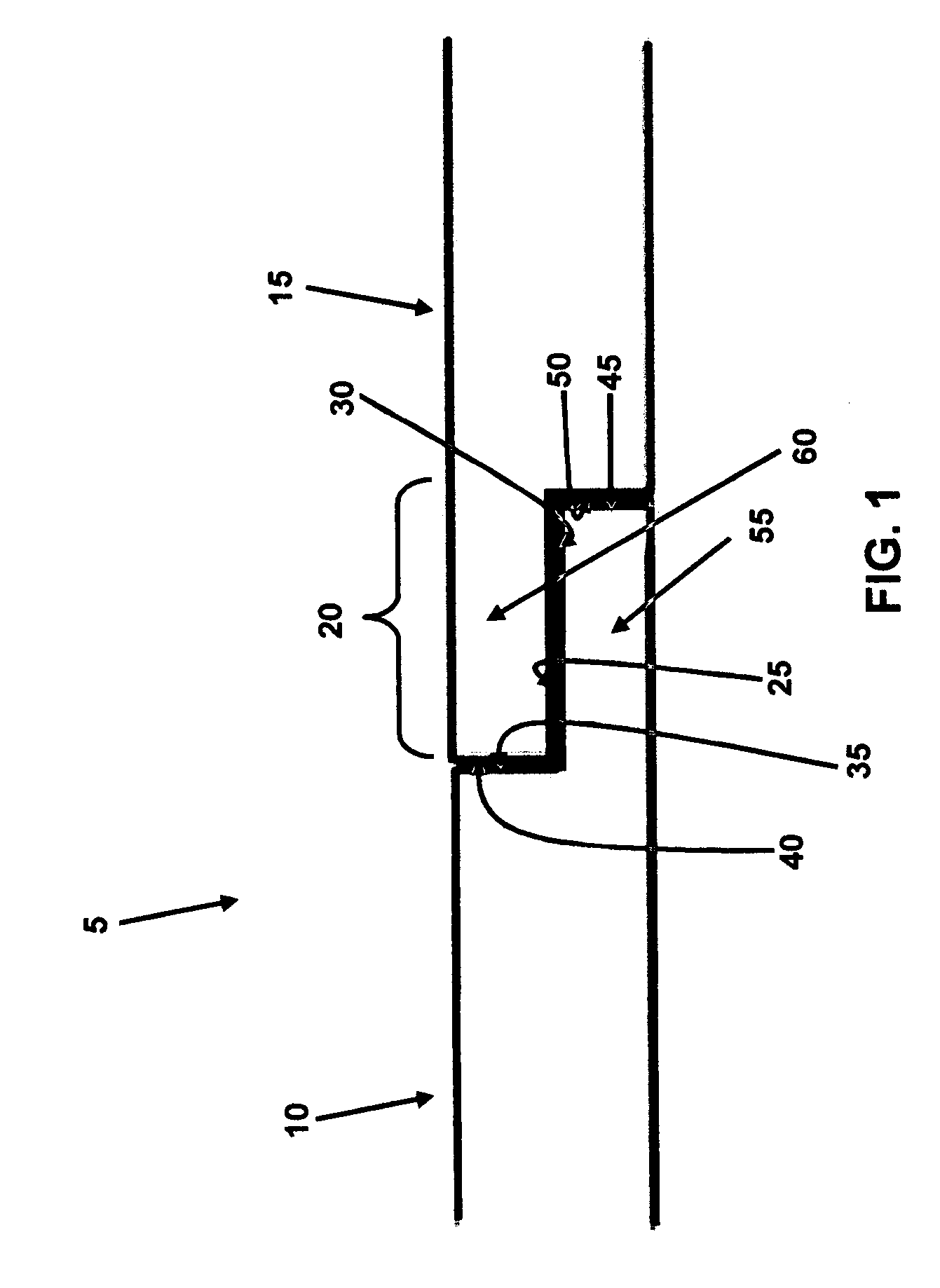
[0068] Looking first at FIGS. 1 and 2, there is shown a novel composite guidewire 5 formed in accordance with the present invention. Novel composite guidewire 5 generally comprises a first wire segment 10 and a second wire segment 15. First wire segment 10 and second wire segment 15 are attached to one another at a joint 20.

[0069] First wire segment 10 and second wire segment 15 are preferably formed out of different materials, in order to permit composite guidewire 5 to have different characteristics along its length.

[0070] In one preferred form of the present invention, composite guidewire 5 comprises a vascular guidewire, with first wire segment 10 comprising the proximal portion of the composite guidewire and second wire segment 15 comprising the distal portion of the composite guidewire. To this end, proximal wire segment 10 generally requires lower elasticity and higher stiffness, in order to provide sufficient column strength to ensure adequate pushability of the guidewire ...


PUM

PropertyMeasurementUnit
Lengthaaaaaaaaaa
Diameteraaaaaaaaaa
Elasticityaaaaaaaaaa

Abstract

A composite guidewire comprising a proximal wire segment having a proximal end, a distal end and a longitudinal axis extending therebetween, the distal end being formed with a first flat planar bonding face which extends parallel to the longitudinal axis, the proximal wire segment having a first elasticity; a distal wire segment having a proximal end, a distal end and a longitudinal axis extending therebetween, the proximal end being formed with a second flat planar bonding face which extends parallel to the longitudinal axis, the distal wire segment having a second elasticity; wherein the first and second flat planar bonding faces of the proximal wire segment are formed complementary to one another; and further wherein the proximal and distal wire segments are joined together by bonding the first flat planar bonding face to the second flat planar bonding face in an overlapping manner and a method for forming a composite guidewire.

Description

REFERENCE TO PENDING PRIOR PATENT APPLICATION [0001] This patent application claims benefit of pending prior U.S. Provisional Patent Application Ser. No. 60 / 799,985, filed May 12, 2006 by Eric D. Mathews et al. for NOVEL COMPOSITE CONSTRUCTION AND METHOD FOR MAKING THE SAME (Attorney's Docket No. CONCERT-1 PROV), which patent application is hereby incorporated herein by reference.FIELD OF THE INVENTION [0002] This invention relates to medical apparatus and methods in general, and more particularly to medical guidewires and methods for making the same. BACKGROUND OF THE INVENTION [0003] Guidewires are widely used in medical procedures. Vascular guidewires, for example, are commonly used to guide catheters through tortuous vasculature to distal sites. By way of example but not limitation, a guidewire used for delivering coronary stents might enter the patient's body down at the femoral artery, traverse the intervening vasculature, and terminate in a coronary artery. An orthopedic arth...

Claims


Application Information

Patent Timeline
IPC IPC(8): A61M5/178
CPCA61M25/09A61M25/0905A61M2025/09075Y10T403/63Y10T403/5773Y10T403/635A61M2025/09108
Inventor MATHEWS, ERIC D.WHITEHEAD, ANDREW M.PANICCI, JOHN R.
Owner CONCERT MEDICAL
Learn More