
Humeral Head Prosthesis

a prosthesis and humeral head technology, applied in the field of shaftless shoulder joint prosthesis, can solve the problem of significant impeded access to the joint sock

Active Publication Date: 2007-12-06
SQ PRODS
View PDF9 Cites 29 Cited by
  • Summary
  • Abstract
  • Description
  • Claims
  • Application Information

AI Technical Summary

Benefits of technology

[0011] Another advantage of the shaftless humeral head prosthesis proposed according to the invention is that implantation is possible independently of the geometry of the humeral shaft. Especially in the case of previous humeral fractures, a displacement of the fractured head calotte relative to the humerus often occurs. Here the humerus is often shifted in the anterior and medial direction, while the head segment is displaced in the posterior and lateral direction. The ability to use conventional shaft prostheses can then be significantly hampered since introduction of the shaft into the bone marrow space is impeded by the offset and the medial offset may be too large.
[0012] Finally, what must be mentioned as advantages of the shaftless humeral head prosthesis proposed according to the invention are the relatively simple manipulation and reliable and proven cement-free anchoring by means of the hollow screw proposed according to the invention. In addition, it is possible to provide a wide array of implant sizes, thereby enabling the anatomically correct restoration of the joint by means of the modular design.

Problems solved by technology

Accessibility to the joint socket is thus significantly impeded due to the fact that the joint head is essentially maintained.

Method used


Image

  • Humeral Head Prosthesis
  • Humeral Head Prosthesis
  • Humeral Head Prosthesis

Examples


Embodiment Construction

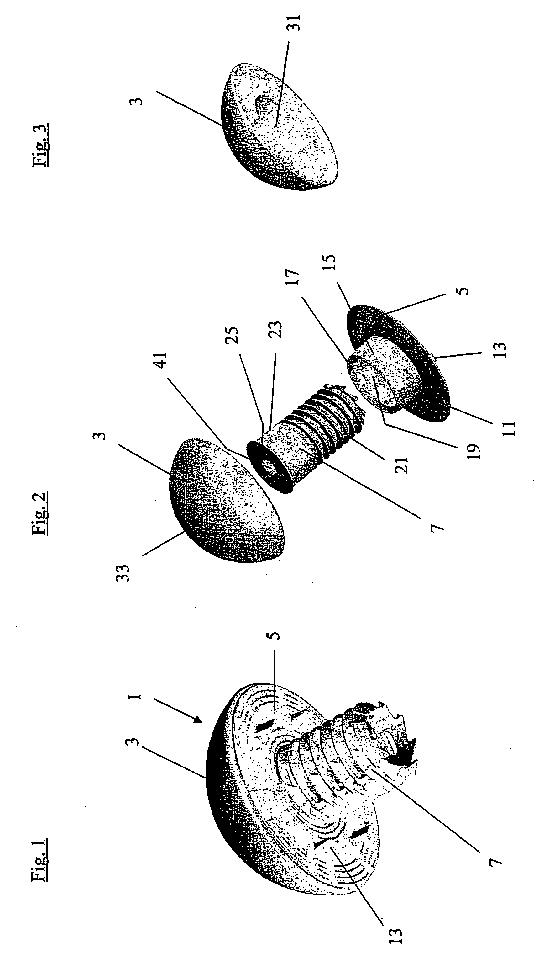
[0019]FIG. 1 is a perspective view illustrating a humeral head prosthesis 1 according to the invention seen laterally from below, including a joint head 3 which is mounted on a pressure disk 5 and is essentially abutting this disk. A hollow screw 7 is fitted so as to project medially through pressure disk 5, said screw being provided in order to affix joint head 3 along with pressure disk 5 within or on the bone. Also seen are the downward-protruding fixation hooks or lugs 13 which rotationally fix the pressure disk to the bone.

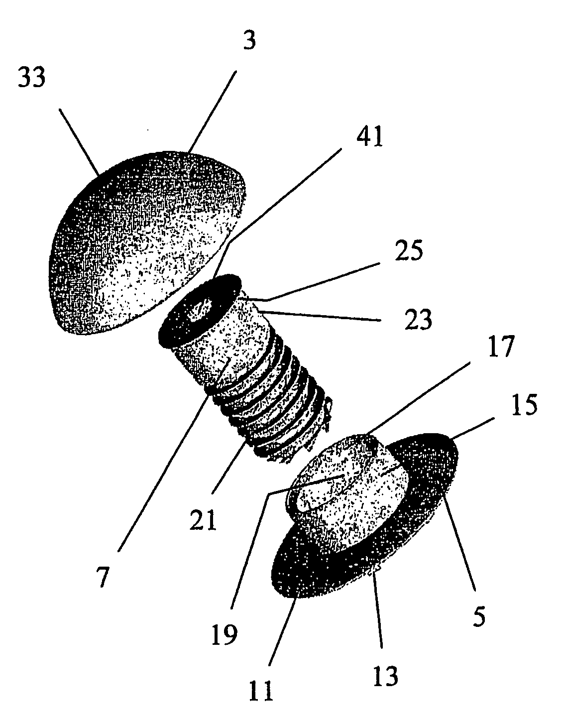
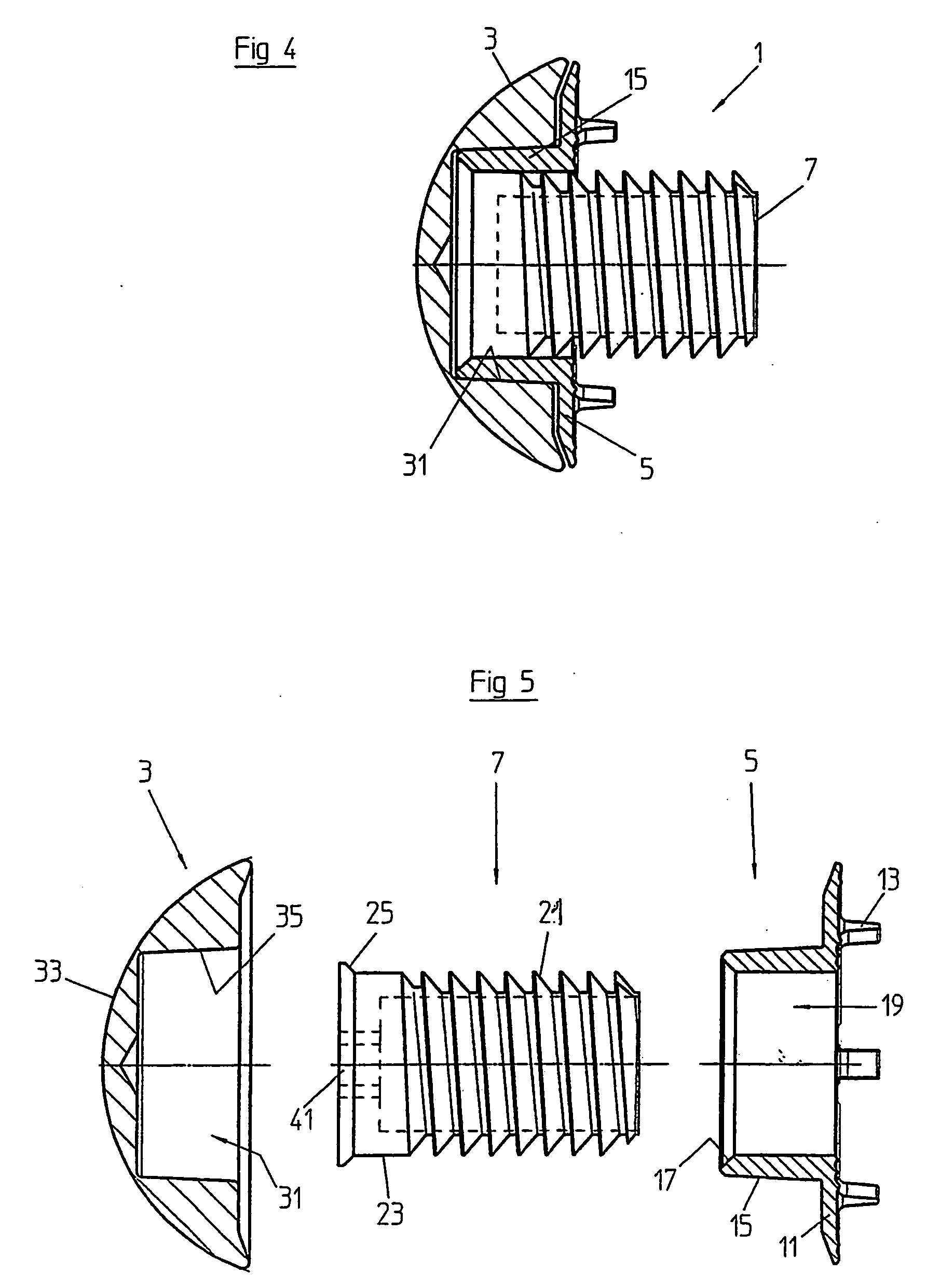
[0020]FIG. 2 is another perspective view of the prosthesis of FIG. 1—illustrating it, however, when disassembled into individual components. Evident here is joint head 3 including the at least nearly spherical joint surface 33. Hollow screw 7 has a thread 21 with which to fix the hollow screw within the bone. For this purpose, hollow screw 7 is driven into the bone through a medial hole 19 of pressure disk 5. In addition, hollow screw 7 has one at least esse...


PUM


Abstract

A shoulder joint prosthesis has an at least two-pieced humeral head prosthesis, comprising a calotte, or a joint head (3) and a fixing body (5, 7). The latter comprises a fixing piece (15), for detachable connection of the calotte and a mounting section (21), for the at least cement-free anchoring of the fixing device in the bone. The fixing body is preferably of two-piece embodiment, comprising a discoid positioning body (5) with a medial hole and an anchoring body (7), provided for fixing the positioning body (7) to the bone through the medial hole (19).

Description

Related Application [0001] This application is a U.S. national stage filing under 35 U.S.C. §371 of International Application No. PCT / CH2005 / 000011 filed Jan. 13, 2005 and claiming priority under 35 U.S.C. §119 of Switzerland patent application no. 82 / 04 filed Jan. 22, 2004.TECHNICAL FIELD [0002] The invention relates to a shaftless shoulder joint prosthesis, and to a method of fitting a shoulder joint prosthesis. BACKGROUND [0003] Particularly in the case of young patients, or patients in whom the bone substance is well preserved, care must be taken that as little bone substance as possible is lost when fitting a shoulder prosthesis. Another important requirement is that mobility be preserved, while at the same time maintaining joint stability. [0004] Already known in this regard are so-called cup shoulder prostheses which are offered by, among others, the companies Centerpulse and Biomet Orthopedics. With these so-called cup shoulder prostheses, the head component is fixed to the ...

Claims


Application Information

Patent Timeline
IPC IPC(8): A61F2/40A61F2/00A61F2/30
CPCA61F2/4003A61F2002/30332A61F2002/30604A61F2002/3085A61F2002/4007A61F2220/0033A61F2310/00023A61F2310/00029A61F2002/4037
Inventor HABERMEYER, PETERKALIN, PETER
Owner SQ PRODS
Learn More