Lighting performance power monitoring system and method with optional integrated light control

a technology of power monitoring system and light control, which is applied in the direction of process and machine control, electric devices, instruments, etc., can solve the problems of changing characteristics of electric power consumption of lighting systems, and achieve the effects of reducing over-all material and labor costs, physical space requirements, and conserving energy

Active Publication Date: 2007-12-06
GRIDPOINT
View PDF7 Cites 59 Cited by
  • Summary
  • Abstract
  • Description
  • Claims
  • Application Information

AI Technical Summary

Benefits of technology

[0028] The invention can also be incorporated into a system which integrates lighting performance monitoring, as discussed above, and lighting control. Electrical load switching devices are normally provided so that building lights can be turned on or off based on building occupancy. This is done to conserve energy and to inform the public when facilities are open business. Such load switching capability may be provided through lighting control units that are designed to serve multiple lighting circuits under the control of timers, daylight sensors (photocells, etc.), or more sophisticated energy management systems. This embodiment provides for the integration of lighting performance monitoring with lighting control units to reduce over-all material and labor costs as well as physical space requirements.

Problems solved by technology

As lighting system components fail, such as bulbs and ballasts, the electric power consumption of the lighting system changes characteristics.

Method used


Image

  • Lighting performance power monitoring system and method with optional integrated light control
  • Lighting performance power monitoring system and method with optional integrated light control
  • Lighting performance power monitoring system and method with optional integrated light control

Examples


Embodiment Construction

[0058] In the following discussions for purposes of clarity with respect to explaining the current invention, common components are numbered according to their first appearance in a drawing and well-known components are to be interpreted according to the understanding of a person ordinarily skilled in the art, e.g., wide area network (WAN) and Bluetooth are well-known in the art and are not described but given their well-known meanings.

Lighting Performance Monitor

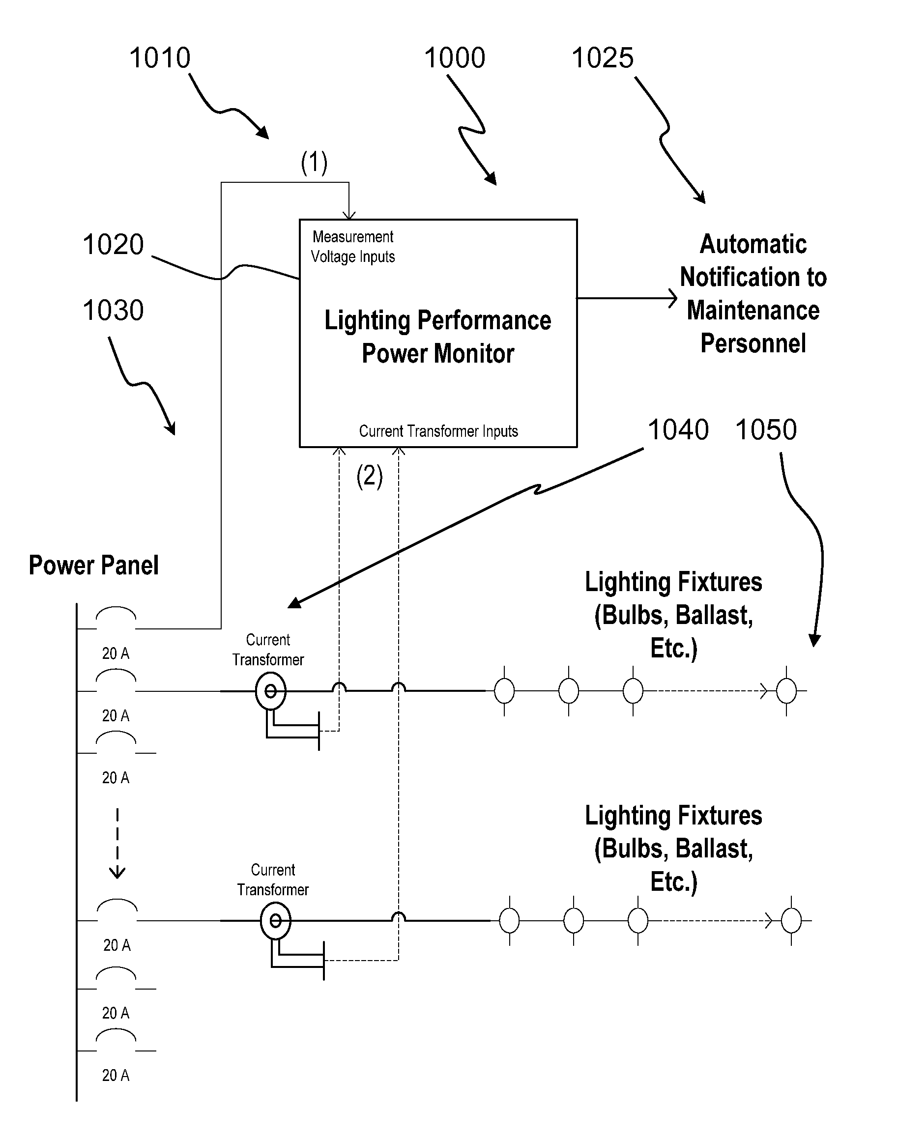
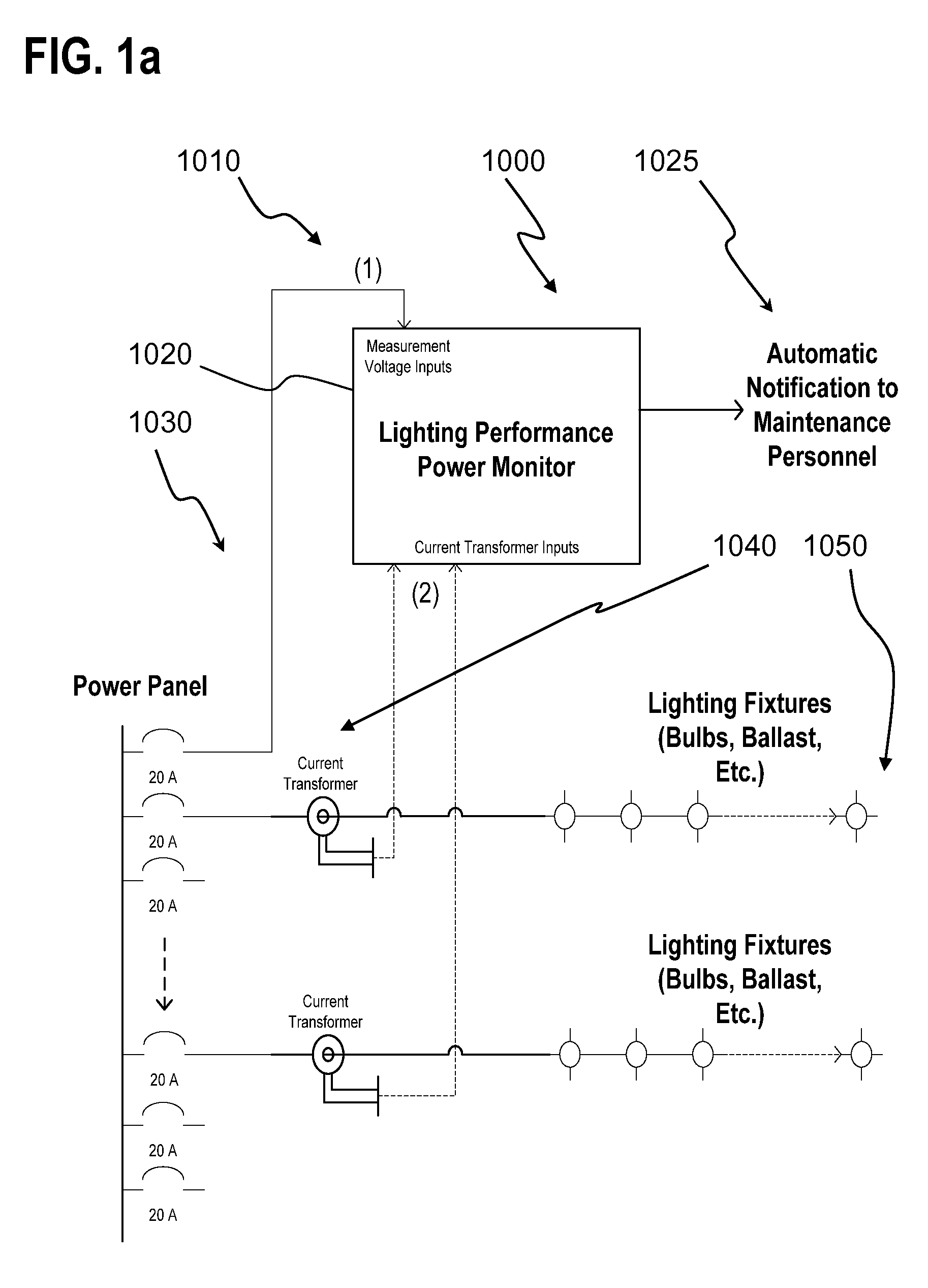
[0059]FIG. 1a is a schematic of an embodiment of a lighting performance monitor according to the present invention. As shown in the drawing, the lighting performance power monitor 1000 includes voltage measurement inputs 1010 and current transformer inputs 1020. There is a power panel 1030 from which a plurality of circuits light up different zones, (e.g. areas) of a particular retail establishment, office, etc. Both the voltage and the current waveforms are sampled to calculate the electrical load, such as power (watts)...


PUM


Abstract

A light performance monitoring device and optionally integrated controller includes a monitor module that directly monitors energy usage of at least one energy load to generate at least one measurement of energy usage; a storage module stores a series of baseline values of energy usage of the energy load, a comparator module compares energy measurements made at predetermined intervals with the baseline values, and a notification module notifies a designated recipient that there is a deviation from the baseline values consistent with a burned out or non-operational light fixture, including but not limited to light bulbs or ballast devices. A control module optionally integrated with the light performance monitoring device can be operatively coupled to the monitor module to control energy usage by the at least one energy load via a data link in a pre-determined manner that is based on the at least one measurement of energy usage.

Description

CROSS REFERENCE TO RELATED APPLICATION [0001] The present application claims the benefit of U.S. provisional patent application No. 60 / 795,644, filed Apr. 28, 2006, incorporated herein by reference in its entirety.FIELD OF THE INVENTION [0002] The present invention relates to monitoring systems and methods for detecting power usage and control of lighting systems. More particularly, the present invention provides an automated notification system that a light monitoring system requires replacement of items such as bulbs, ballasts, which may or may not be integrated with a lighting control / actuation system. BACKGROUND OF THE INVENTION [0003] Maintaining adequate interior and exterior lighting levels is a significant endeavor for many building facility operators. Maintaining proper light intensity is considered to be an important factor for various building usages, including: [0004] (a) Facilitating retail sales from display floor areas; retail store operators have disclosed that there...

Claims


Application Information

Patent Timeline
Patent Type & Authority Applications(United States)
IPC IPC(8): G01R21/00G06F11/30G08B21/00
CPCG01R19/2513G01R22/10H05B37/02G01R31/44G01R21/133H05B47/17H05B47/10H05B47/165
Inventor HOWELL, DONALD W.VINSON, MARK W.BLEVINS, FRANK O.TAMAGNI, ARMAND J. JR.CAMPBELL, MICHAEL L.
Owner GRIDPOINT
Why Eureka
Try Eureka