Clamp Device for Connection

a technology of a clamping device and a connection rod, which is applied in the direction of hose connection, snap fastener, buckle, etc., can solve the problems of affecting the normal function of the band, the screw worm is damaged, and the manufacturing cost is increased, so as to achieve the effect of increasing the meshing area

Inactive Publication Date: 2007-12-13
TAKAGI MFG
View PDF9 Cites 8 Cited by
  • Summary
  • Abstract
  • Description
  • Claims
  • Application Information

AI Technical Summary

Benefits of technology

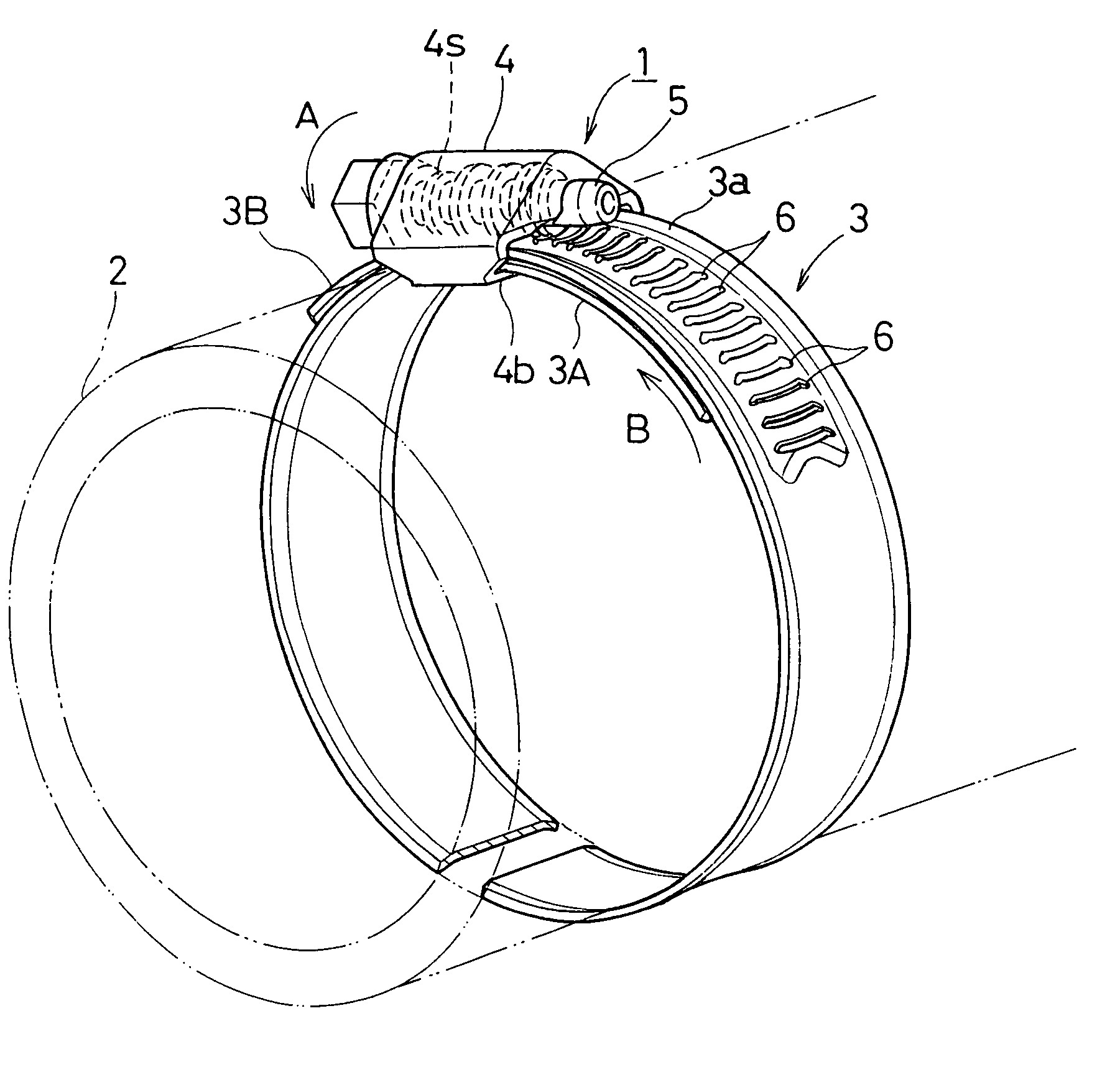
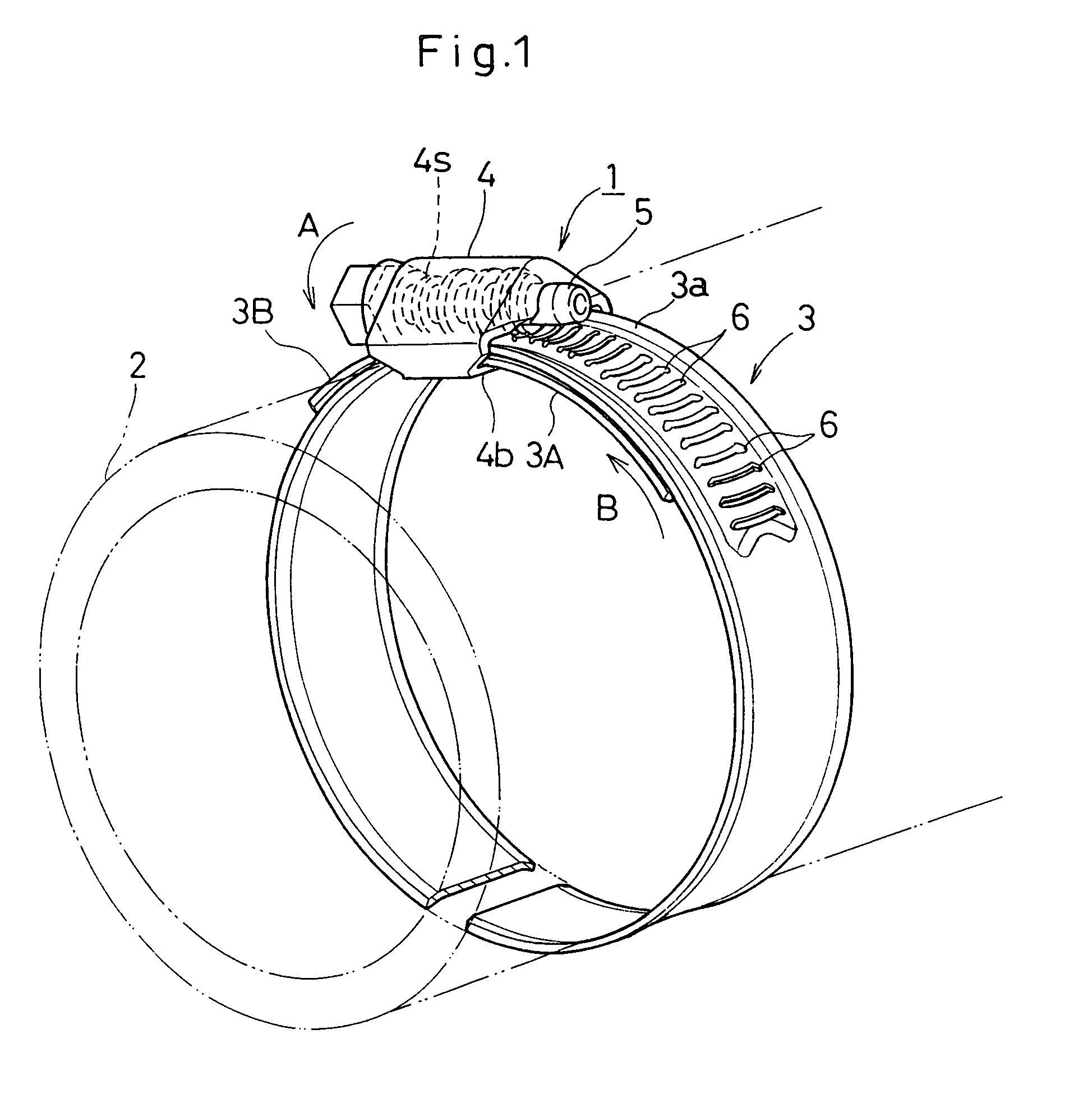
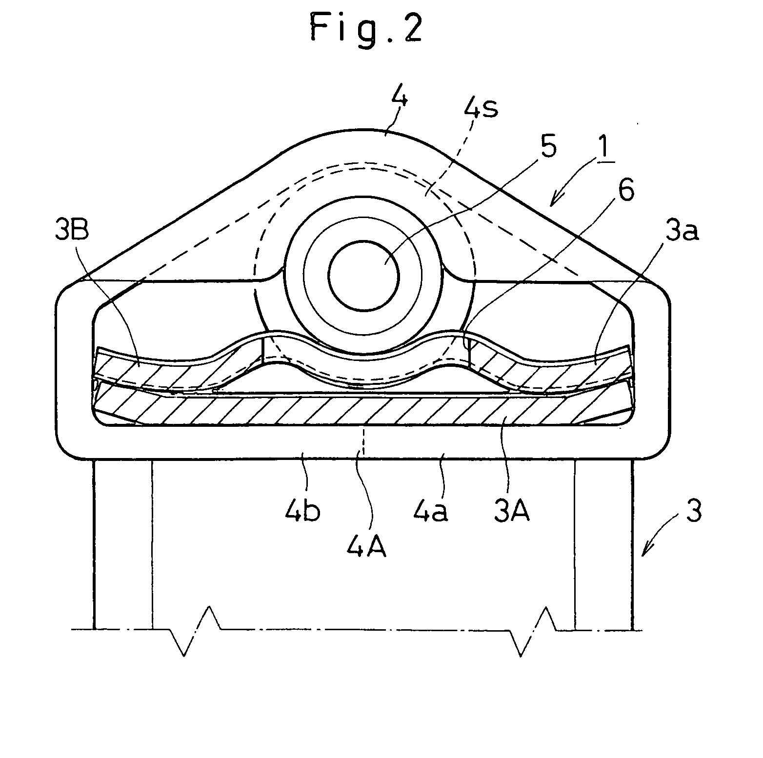
[0015] According to the invention, there is provided a clamping device for connection in which a strap band formed into an open-end annular configuration so as to be tightly wound around a connecting portion to be connected. A housing is fixed to one end portion of the strap band in its circumferential direction with a worm screw rotatably accommodated into the housing. An array of teeth portion is arranged on the other end of the strap band so that the teeth portion comes to mesh with the worm screw within the housing, so as to tighten the strap band against the connecting portion by rotating the worm screw against the array of teeth portion. The other end portion of the strap band in which the array of teeth portion resides, is formed into a wavy and concavo-convex configuration in a width direction of the strap band, so as to increase a meshing area of the array of teeth portion against the worm screw.
[0016] With the array of teeth portion formed into the wavy and concavo-convex configuration in the width direction, it is possible to increase a contact area or sliding pressure between the worm screw and the array of teeth portion. While at the same time, the array of teeth portion increases its bending rigidity to improve the physical strength in the direction in which the array of the teeth portion is subjected to the sliding pressure from the worm screw.
[0017] This makes it possible to mesh the array of teeth portion of high bending rigidity with the worm screw through an enlarged contact area, thus spreading the sliding pressure of the worm screw against the array of teeth portion so as to decrease the sliding pressure per a unit area. As a result, it becomes possible to maintain a good meshing condition between the worm screw and the array of teeth portion for an extended period of time without doing damage on the worm screw and the teeth portion upon tightly meshing the worm screw with the array of the teeth portion.

Problems solved by technology

Under the above structure, it becomes necessary to apply a larger amount of tightening force to the band so as to increase a sliding pressure of the worm screw against the slantwise grooves, thus producing a possibility to do damage on the screw worm and the slantwise grooves so as to lose the normal function of the band.
For this reason, a large amount of the reactionary force increases the sliding pressure of the worm gear against the gear grooves to do damage on the gear grooves or excessively wear the valley portion of the worm gear so as to bring it out of mesh especially when tightly winding the band.
This is effective in compensating the tightening force of the band by an amount in which the rubber hose contracts although it raises a manufacturing cost due to an increased number of component parts with a complicated structure.
This increases the sliding pressure of the screw bolt against the teeth portion to do damage on the teeth portion and the screw bolt.
In any of the documents mentioned above, it is not sufficient to cope with the above inconveniences especially when tightening the strap with the increased torque.

Method used


Image

  • Clamp Device for Connection
  • Clamp Device for Connection
  • Clamp Device for Connection

Examples


second embodiment

of the Invention

[0066]FIG. 9 shows a second embodiment of the invention in which the connection lugs 4a, 4b are ironed out to reduce their thickness by means of a forging procedure. The connection lugs 4a, 4b are reduced at their thickness while insuring the necessary bending and torsional rigidity for the connection lugs 4a, 4b. A relationship (b4a, 4b and a thickness (b) of an elevational side of the housing 4. This makes it possible to advantageously save the material cost while insuring the necessary physical strength for the connection lugs 4a, 4b.

[0067] With the thickness of the connection lugs 4a, 4b thus reduced, it is also possible to regulate an advancement of the connection lugs 4a, 4b in their thickness direction. This makes it possible to make the connection lugs 4a, 4b substantially in flush with an inner surface of the strap band 3 even if the bulged degree of the bulged portion 3C is limited to a certain extent. As a result, this enables the strap band 3 to generall...

third embodiment

of the Invention

[0068]FIG. 10 shows a third embodiment of the invention in which streaks of convex portion 7 are provided on an outer flat surface of the housing 4 as reinforcement ribs. With the streaks of convex portions 7 provided on the housing 4, it is possible to reduce a thickness of the housing 4 so as to save the material cost while insuring necessary bending and torsional rigidity for the housing 4.

fourth embodiment

of the Invention

[0069]FIG. 11 shows a fourth embodiment of the invention in which a wider web-like streak of convex portion 7A is provided as a reinforcement rib on a central portion of the outer flat surface of the housing 4.


PUM


Abstract

A clamping device (1) for connection in which a housing (4) rotatably accommodates a worm screw (5) to mesh with an array of teeth portion (6) of a strap band (3). The strap band (3) is diametrically contracted upon operating the worm screw (5) to wind the strap band (3) around a connecting portion (2). One end portion of the strap band (3) in which the array of teeth portion (6) resides, is formed into a wavy and concavo-convex configuration in its width direction, thus increasing a meshing area of the array of teeth portion (6) against the worm screw (5). This makes it possible for the strap band (3) to cope with a situation in which the strap band (3) is required to tightly wind the connecting portion (2) with a high tightening force.

Description

FIELD OF THE INVENTION [0001] The invention relates to a clamping device for connection in which a worm screw is brought into mesh with an array of teeth portion defined on a strap band so as to diametrically contract it upon tightening the strap band around a connecting portion. BACKGROUND OF THE INVENTION [0002] This type of the clamping device has been disclosed by Japanese Utitily Model Publication No. 6-23822, Japanese Laid-open Patent Application No. 61-244906 and Japanese Patent Publication No. 7-26711 (referred to as “first document”,“second document” and “third document” in turn hereinafter). [0003] In the first document, a portion in which slantwise grooves are defined to make a worm screw mesh with the grooves, is swollen in the diametrical direction to distance from a hose-forming section so as to prevent an incidental damage on the hose. This prevents a maximum surface pressure from exerting at the contact portion between a band and the hose, so as for the band not to s...

Claims


Application Information

Patent Timeline
Patent Type & Authority Applications(United States)
IPC IPC(8): F16L33/08
CPCF16L33/08Y10T24/1427Y10T24/1416Y10T24/1457Y10T24/1441
Inventor ITO, NORIONIWA, MIKIO
Owner TAKAGI MFG
Why Eureka
Try Eureka