Orientation insensitive thermosiphon capable of operation in upside down position

a technology of orientation insensitive thermosiphon and upside-down position, which is applied in the direction of lighting and heating apparatus, instruments, and semiconductor/solid-state device details, etc., can solve the problem of relatively low air heat capacity

Inactive Publication Date: 2007-12-13
DELPHI TECH INC
View PDF13 Cites 56 Cited by
  • Summary
  • Abstract
  • Description
  • Claims
  • Application Information

AI Technical Summary

Problems solved by technology

Heat exchangers and heat sink assemblies have been used that apply natural or forced convection cooling methods to dissipate heat from electroni

Method used


Image

  • Orientation insensitive thermosiphon capable of operation in upside down position
  • Orientation insensitive thermosiphon capable of operation in upside down position
  • Orientation insensitive thermosiphon capable of operation in upside down position

Examples


Embodiment Construction

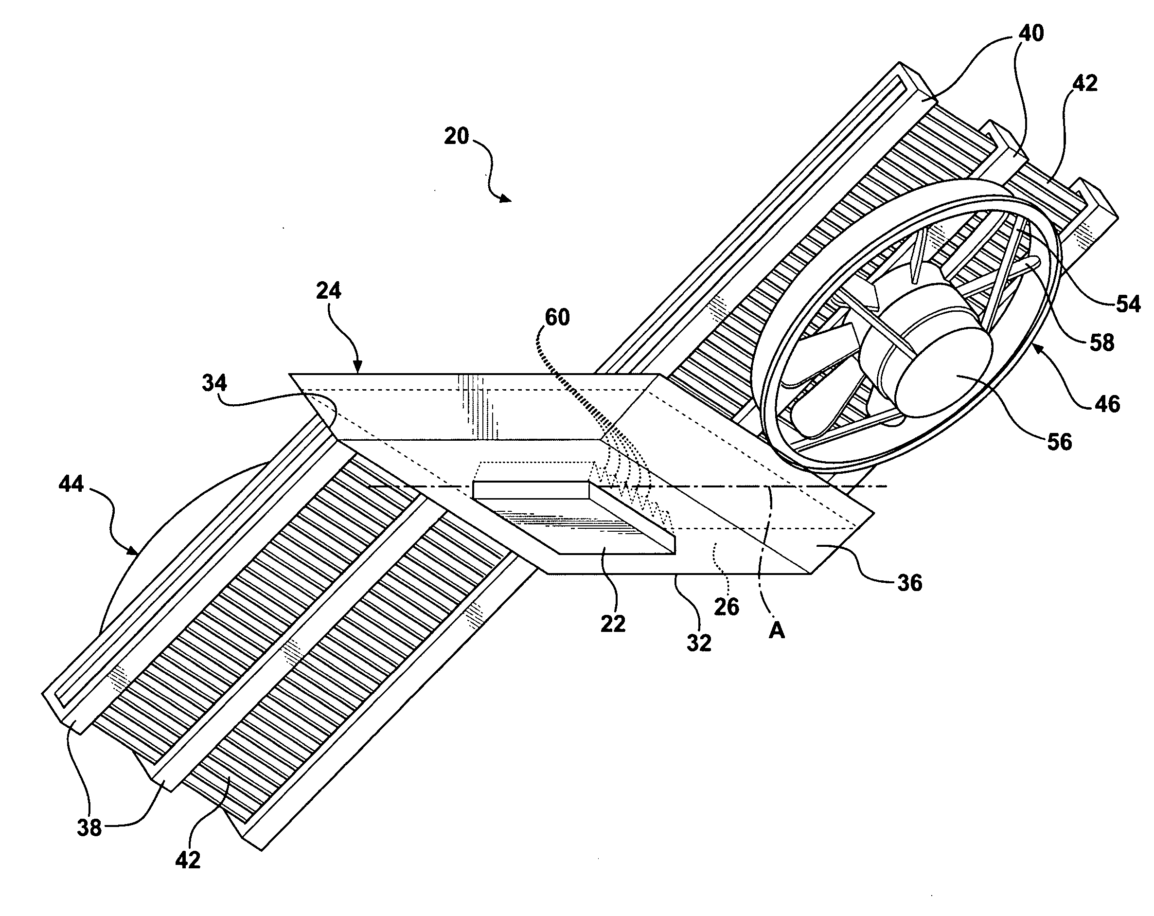
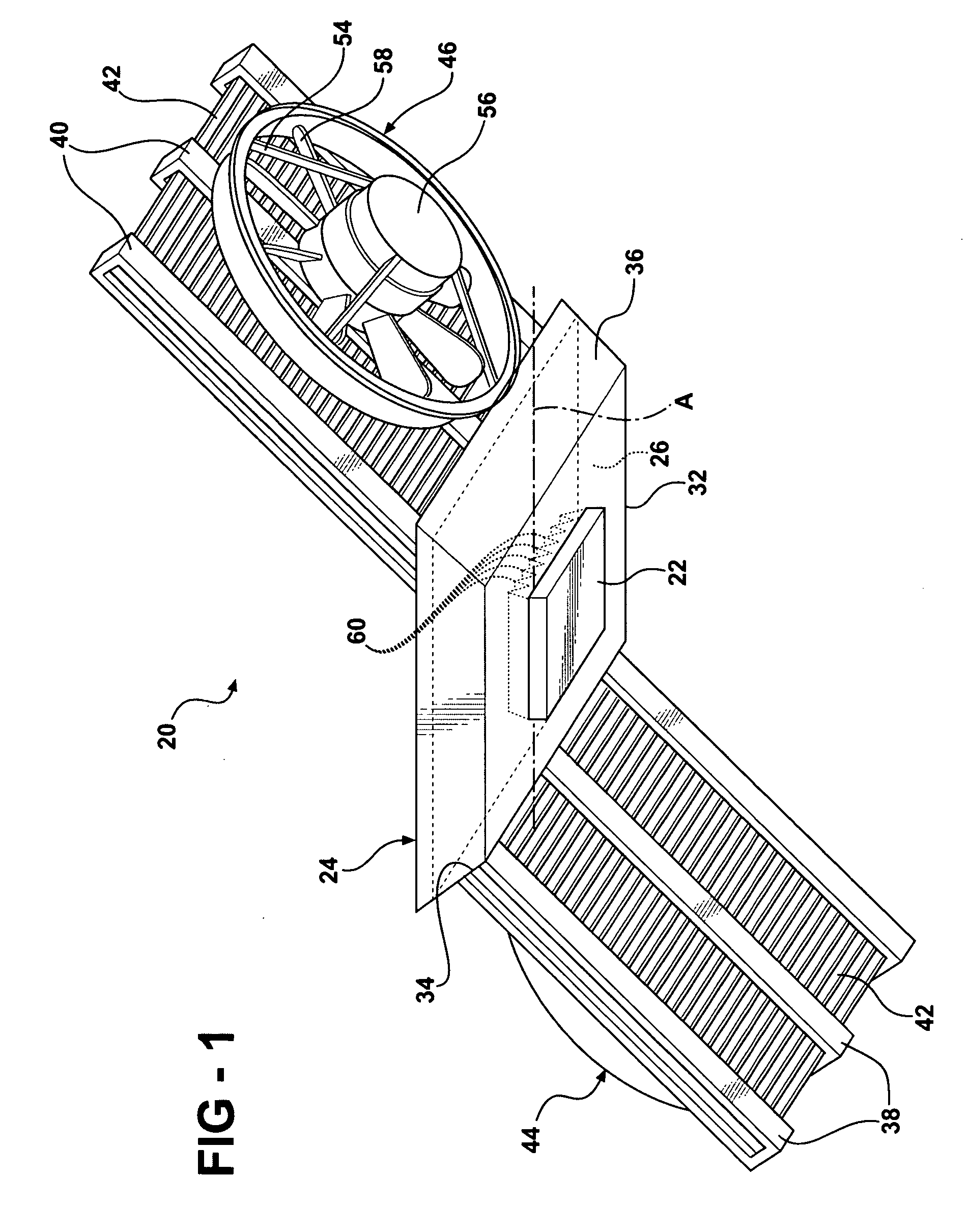
[0018]Referring to the Figures, wherein like numerals indicate corresponding parts throughout the several views, a heat exchanger assembly 20 is generally shown for cooling an electronic device 22.

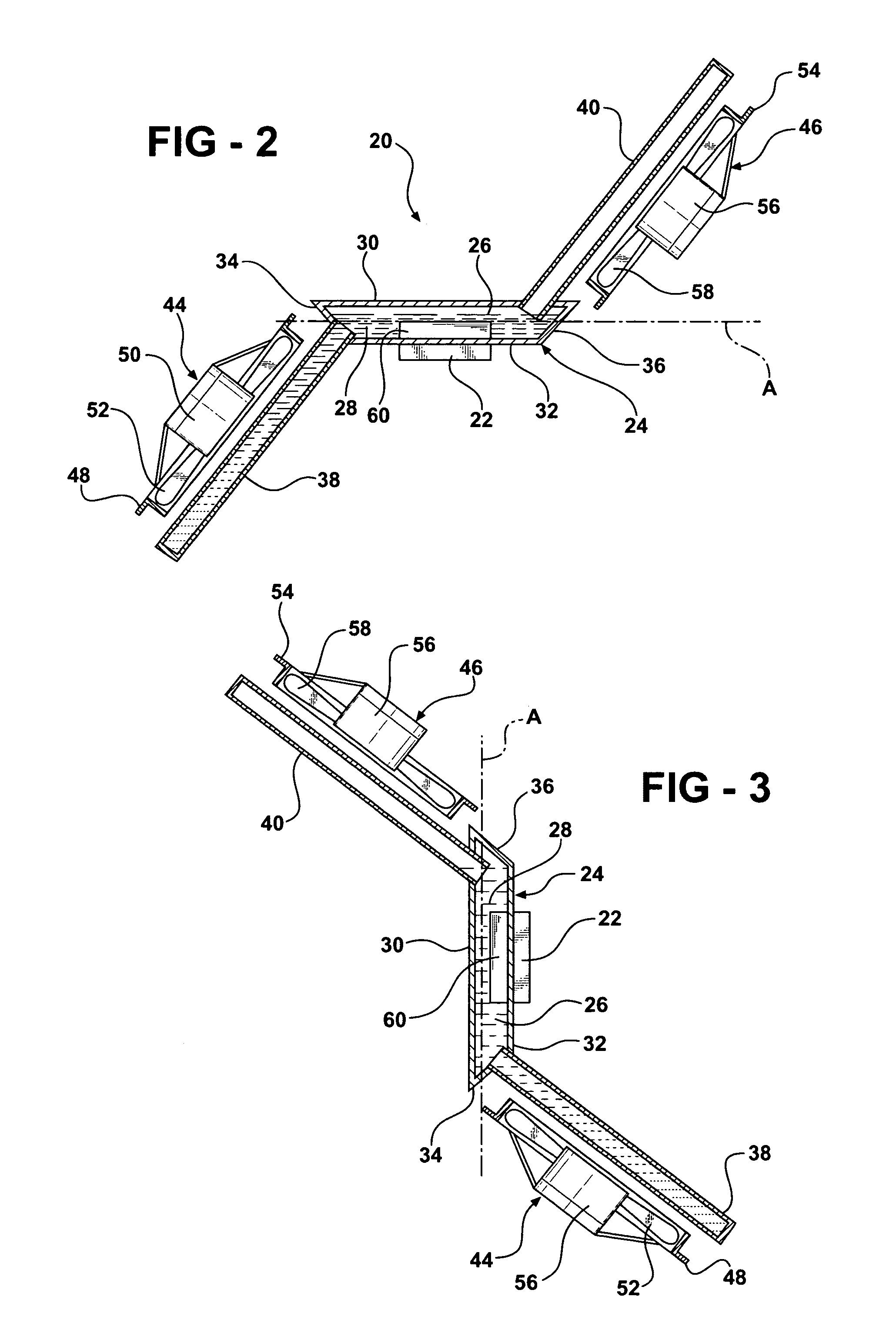
[0019]The assembly 20 includes a housing 24 generally indicated which defines a boiling chamber 26 extending along an axis A between opposite ends for containing a refrigerant 28 to undergo a liquid-to-vapor-to-condensate cycle. The housing 24 has a top wall 30 and a bottom wall 32 both extending axially and a first end wall 34 and a second end wall 36 both extending from the bottom wall 32 upwardly and outwardly to the top wall 30 forming opposite angled or oppositely flared end walls 34, 36.

[0020]A plurality of first condensing tubes 38 and a plurality of second condensing tubes 40 extend axially from the housing 24 for condensing vapor boiled from the refrigerant 28. The first condensing tubes 38 extend in one direction from the boiling chamber 26 at a first predetermined angle from the...


PUM


Abstract

The invention provides a heat exchanger assembly having a housing which defines a boiling chamber extending along an axis between opposite ends. A plurality of first condensing tubes extend axially and downwardly in one direction at a first predetermined angle to and below the axis (A) from the housing and a plurality of second condensing tubes extend axially and upwardly in the opposite direction at the same predetermined angle to and above the axis (A) from the housing. The volume of refrigerant in the housing is greater than the volume of the second condensing tubes and the volume of the boiling chamber.

Description

BACKGROUND OF THE INVENTION[0001]1. Field of the Invention[0002]The invention relates to a heat exchanger assembly for cooling an electronic device.[0003]2. Description of the Prior Art[0004]The operating speed of computers is constantly being improved to create faster computers. With this, comes an increase in heat generation and a need to effectively dissipate that heat.[0005]Heat exchangers and heat sink assemblies have been used that apply natural or forced convection cooling methods to dissipate heat from electronic devices that are highly concentrated heat sources such as microprocessors and computer chips; however, air has a relatively low heat capacity. Thus, liquid-cooled units called LCUs employing a cold plate in conjunction with high heat capacity fluids have been used to remove heat from these types of heat sources. Although, LCUs are satisfactory for moderate heat flux, increasing computing speeds have required more effective heat sink assemblies.[0006]Accordingly, the...

Claims


Application Information

Patent Timeline
IPC IPC(8): H05K7/20
CPCF28D15/0266F28D15/0233G06F1/206
Inventor BHATTI, MOHINDER SINGHREYZIN, ILYAJOSHI, SHRIKANT MUKUND
Owner DELPHI TECH INC
Why Eureka
Try Eureka