Method and System for Multi-Mode Coverage for an Autonomous Robot

a robot and multi-mode technology, applied in the direction of process and machine control, carpet cleaning, instruments, etc., can solve the problems of inability to vary the control, the robot may become trapped, and the proportion of the area uncovered, so as to optimize the distance the robot travels and effectively covers the area

Inactive Publication Date: 2007-12-13
IROBOT CORP
View PDF57 Cites 80 Cited by
  • Summary
  • Abstract
  • Description
  • Claims
  • Application Information

AI Technical Summary

Benefits of technology

[0018] It is an object of the present invention to provide a system and method to allow a mobile robot to operate in a plurality of modes in order to effectively cover an area.
[0019] It is an object of the present invention to provide a mobile robot, with at least one sensor, to operate in a number of modes including spot-coverage, obstacle following and bounce.
[0020] It is a further object of the invention to provide a mobile robot that alternates between obstacle following and bounce mode to ensure coverage.
[0021] It is an object of the invention to return to spot-coverage after the robot has traveled a pre-determined distance.
[0022] It is an object of the invention to provide a mobile robot able to track the average distance between obstacles and use the average distance as an input to alternate between operational modes.
[0023] It is yet another object of the invention to optimize the distance the robot travels in an obstacle following mode as a function of the frequency of obstacle following and the work width of the robot, and to provide a minimum and maximum distance for operating in obstacle following mode.

Problems solved by technology

Unfortunately, designs in the prior art often leave portions of the area uncovered regardless of the amount of time the device is allowed to complete its tasks.
Failure to achieve complete coverage can result from mechanical limitations—e.g., the size and shape of the robot may prevent it from reaching certain areas—or the robot may become trapped, unable to vary its control to escape.
Failure to achieve complete coverage can also result from an inadequate coverage algorithm.
Due to mechanical and / or algorithmic limitations, certain areas within the available space may be systematically neglected.
Such systematic neglect is a significant limitation in the prior art.
Each of these robots has faced a similar challenge: how to efficiently cover the designated area given limited energy reserves.
Such a positioning system—a positioning system suitably accurate to enable deterministic cleaning might rely on scanning laser rangers, ultrasonic transducers, carrier phase differential GPS, or other methods—can be prohibitively expensive and involve user set-up specific to the particular room geometries.
Also, methods that rely on global positioning are typically incapacitated by the failure of any part of the positioning system.
One example of using highly sophisticated (and expensive) sensor technologies to create deterministic cleaning is the RoboScrub device built by Denning Mobile Robotics and Windsor Industries, which used sonar, infrared detectors, bump sensors and high-precision laser navigation.
The requirement that RoboScrub be able to see at least four targets simultaneously was a significant operational problem.
RoboScrub, therefore, was limited to cleaning large open areas.
Because of the limitations and difficulties of deterministic cleaning, some robots have relied on pseudo-deterministic schemes.
One problem with this technique is wheel slippage.
As shown in FIG. 1B, as the robot 1 navigates about the room, these drive wheel slippage errors accumulate making this type of system unreliable for runs of any substantial duration.
The result of reliance on dead reckoning is intractable systematic neglect; in other words, areas of the floor are not cleaned.
If a calibration spot is moved or blocked or if excessive wheel slippage occurs then Cye can become lost (possibly without realizing that it is lost).
The limitations of practical power supplies, however, usually guarantee that the robot will have insufficient time to clean all areas of a space cluttered with obstacles.
As discussed, the commercially available prior art has not been able to produce an effective coverage algorithm for an area of unknown geometry.
As noted above, the prior art either has relied on sophisticated systems of markers or beacons or has limited the utility of the robot to rooms with simple rectangular geometries.
Attempts to use pseudo-deterministic control algorithms can leave areas of the space systematically neglected.

Method used


Image

  • Method and System for Multi-Mode Coverage for an Autonomous Robot
  • Method and System for Multi-Mode Coverage for an Autonomous Robot
  • Method and System for Multi-Mode Coverage for an Autonomous Robot

Examples


Embodiment Construction

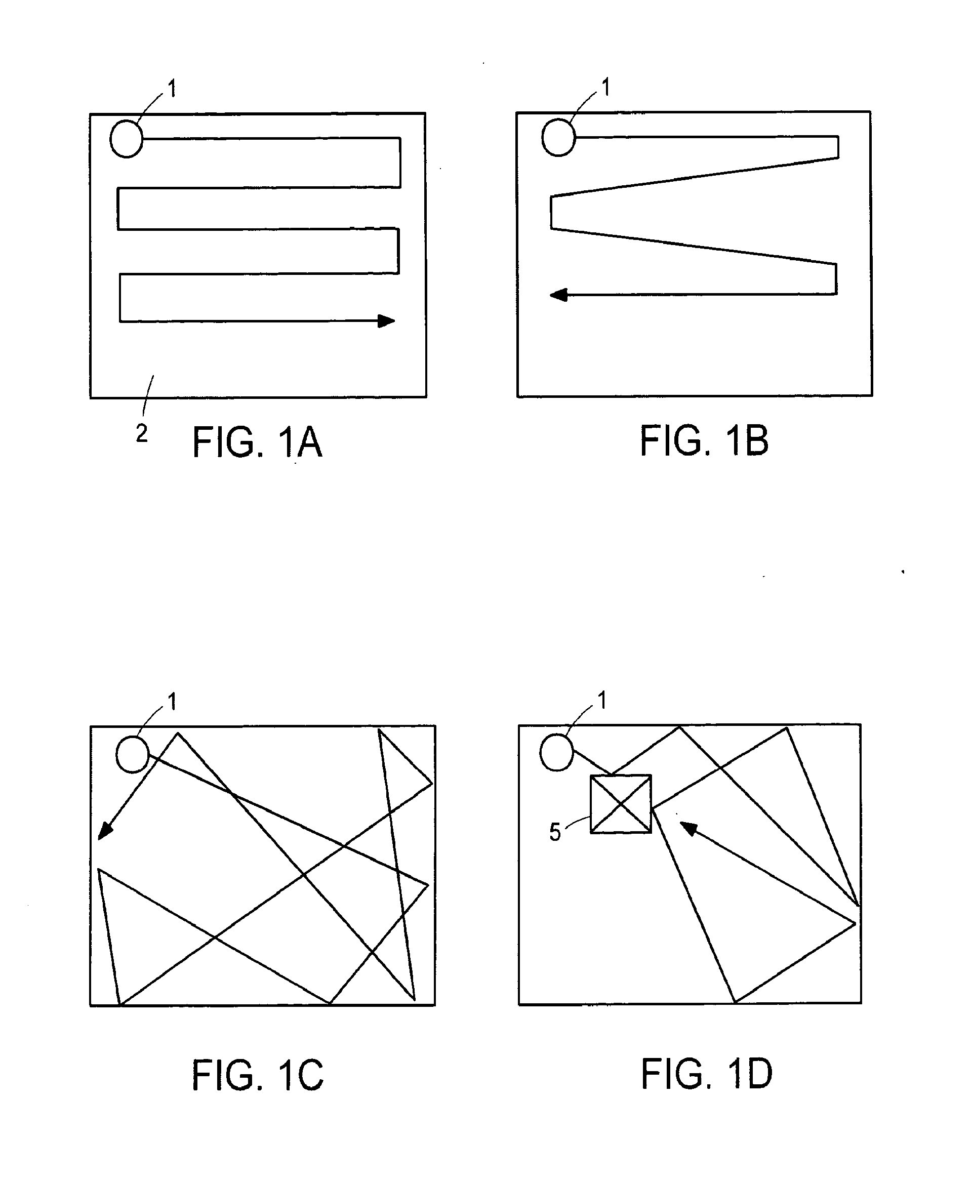
[0043] In the present invention, a mobile robot is designed to provide maximum coverage at an effective coverage rate in a room of unknown geometry. In addition, the perceived effectiveness of the robot is enhanced by the inclusion of patterned or deliberate motion. In addition, in a preferred embodiment, effective coverage requires a control system able to prevent the robot from becoming immobilized in an unknown environment.

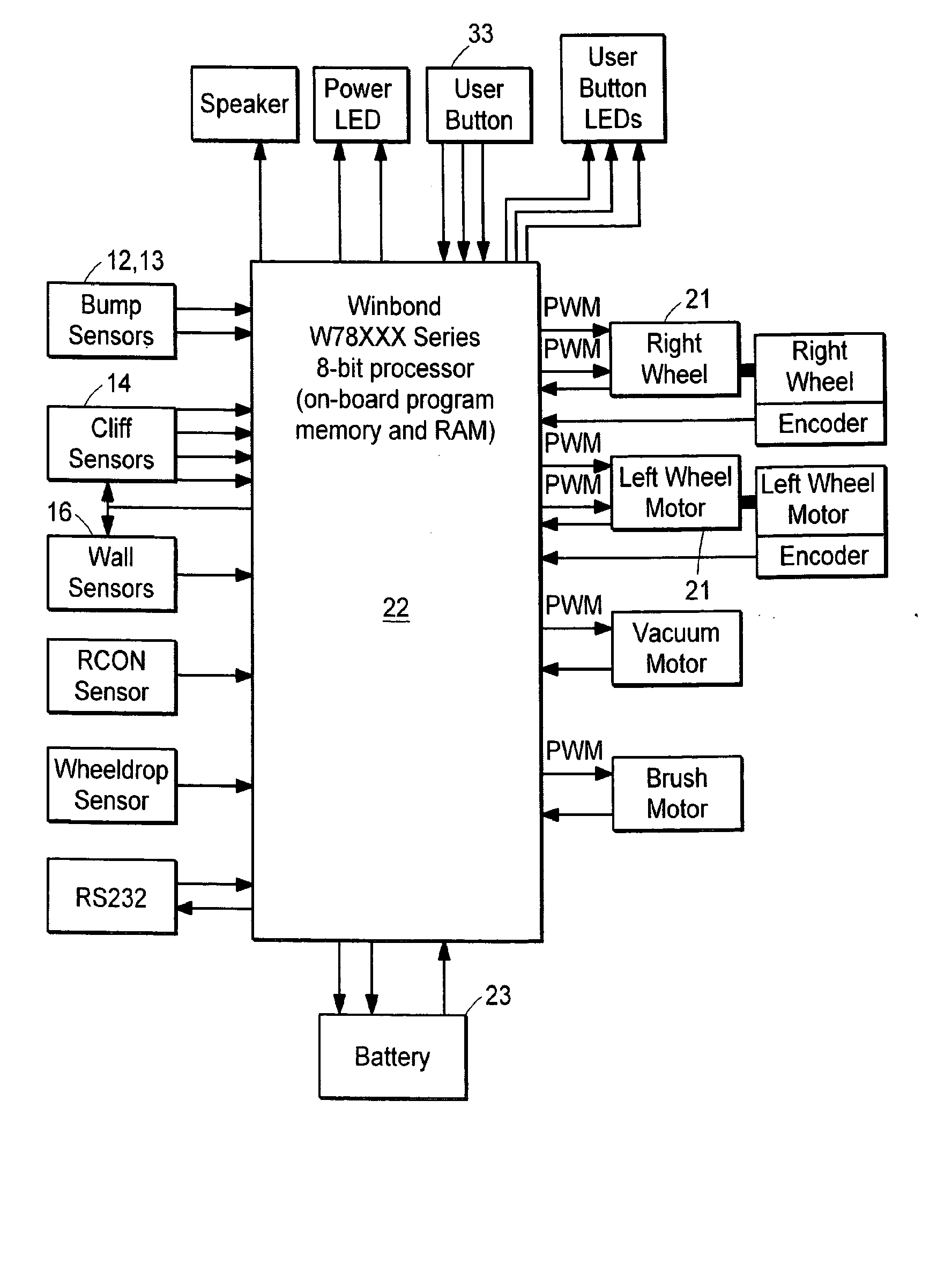
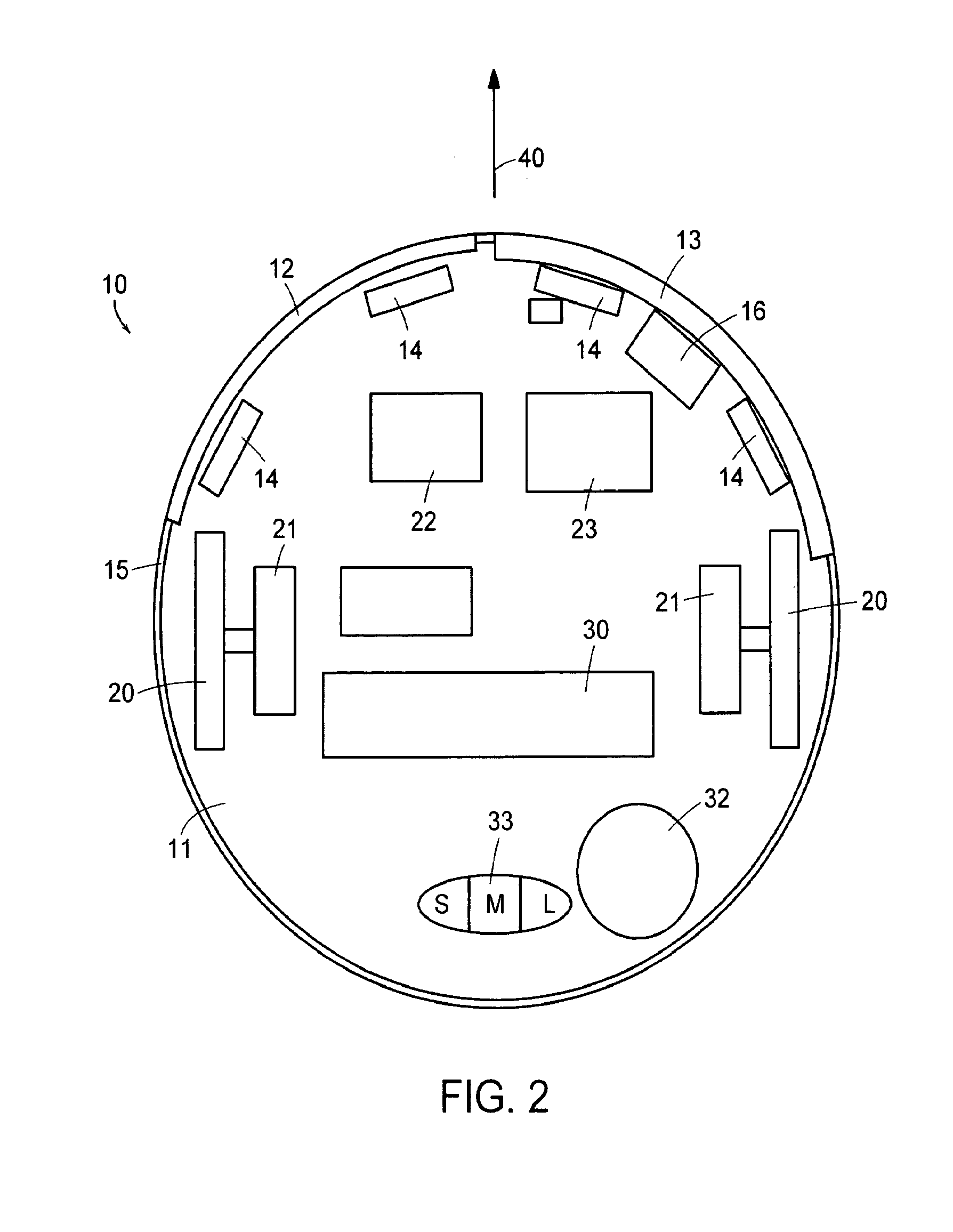
[0044] While the physical structures of mobile robots are known in the art, the components of a preferred, exemplary embodiment of the present invention is described herein. A preferred embodiment of the present invention is a substantially circular robotic sweeper containing certain features. As shown in FIG. 2, for example, the mobile robot 10 of a preferred embodiment includes a chassis 11 supporting mechanical and electrical components. These components include various sensors, including two bump sensors 12&13 located in the forward portion of the robot, f...


PUM


Abstract

A control system for a mobile robot (10) is provided to effectively cover a given area by operating in a plurality of modes, including an obstacle following mode (51) and a random bounce mode (49). In other embodiments, spot coverage, such as spiraling (45), or other modes are also used to increase effectiveness. In addition, a behavior based architecture is used to implement the control system, and various escape behaviors are used to ensure full coverage.

Description

[0001] This application for U.S. patent is a continuation of, and claims priority from, U.S. patent application Ser. No. 10 / 187,851 filed Jun. 12, 2002, entitled Method and System for Multi-Mode Coverage for an Autonomous Robot, and related U.S. Provisional Application for Patent Ser. No. 60 / 297,718 filed Jun. 12, 2001.FIELD OF THE INVENTION [0002] This invention relates generally to autonomous vehicles or robots, and more specifically to methods and mobile robotic devices for covering a specific area as might be required of, or used as, robotic cleaners or lawn mowers. DESCRIPTION OF PRIOR ART [0003] For purposes of this description, examples will focus on the problems faced in the prior art as related to robotic cleaning (e.g., dusting, buffing, sweeping, scrubbing, dry mopping or vacuuming). The claimed invention, however, is limited only by the claims themselves, and one of skill in the art will recognize the myriad of uses for the present invention beyond indoor, domestic clean...

Claims


Application Information

Patent Timeline
Patent Type & Authority Applications(United States)
IPC IPC(8): G05D1/02
CPCG05D1/0219G05D1/0227G05D1/0242G05D1/0255Y10S901/01G05D2201/0203A47L11/00B25J11/0085G05D1/0272B25J9/1694
Inventor JONES, JOSEPH L.MASS, PHILIP R.
Owner IROBOT CORP
Why Eureka
Try Eureka