
Frequency Dividing Systems and Methods

a frequency division and frequency technology, applied in the field of frequency dividers, can solve problems such as signal distortion, harmonics that can be especially problematic, and harmonics contained in signal processing devices

Inactive Publication Date: 2007-12-13
CONEXANT SYST INC +1
View PDF32 Cites 17 Cited by
  • Summary
  • Abstract
  • Description
  • Claims
  • Application Information

AI Technical Summary

Problems solved by technology

Harmonics contained in signal processing devices are a major cause of signal distortions.
One case where harmonics can be especially problematic is in a limiter that is driven by a poly-phase filter.
This shift can, in turn, cause an effective phase error when the output of the poly-phase filter is passed through a limiter that reacts primarily to zero crossings.
An OMP, which is defined as the product of one input and an odd harmonic of another input, can cause signal distortions when its frequency is too close to the frequency of a desired mixer output signal.
Other cases where harmonics can cause signal distortions include, for example, where unwanted harmonics couple across a circuit.

Method used


Image

  • Frequency Dividing Systems and Methods
  • Frequency Dividing Systems and Methods
  • Frequency Dividing Systems and Methods

Examples


Embodiment Construction

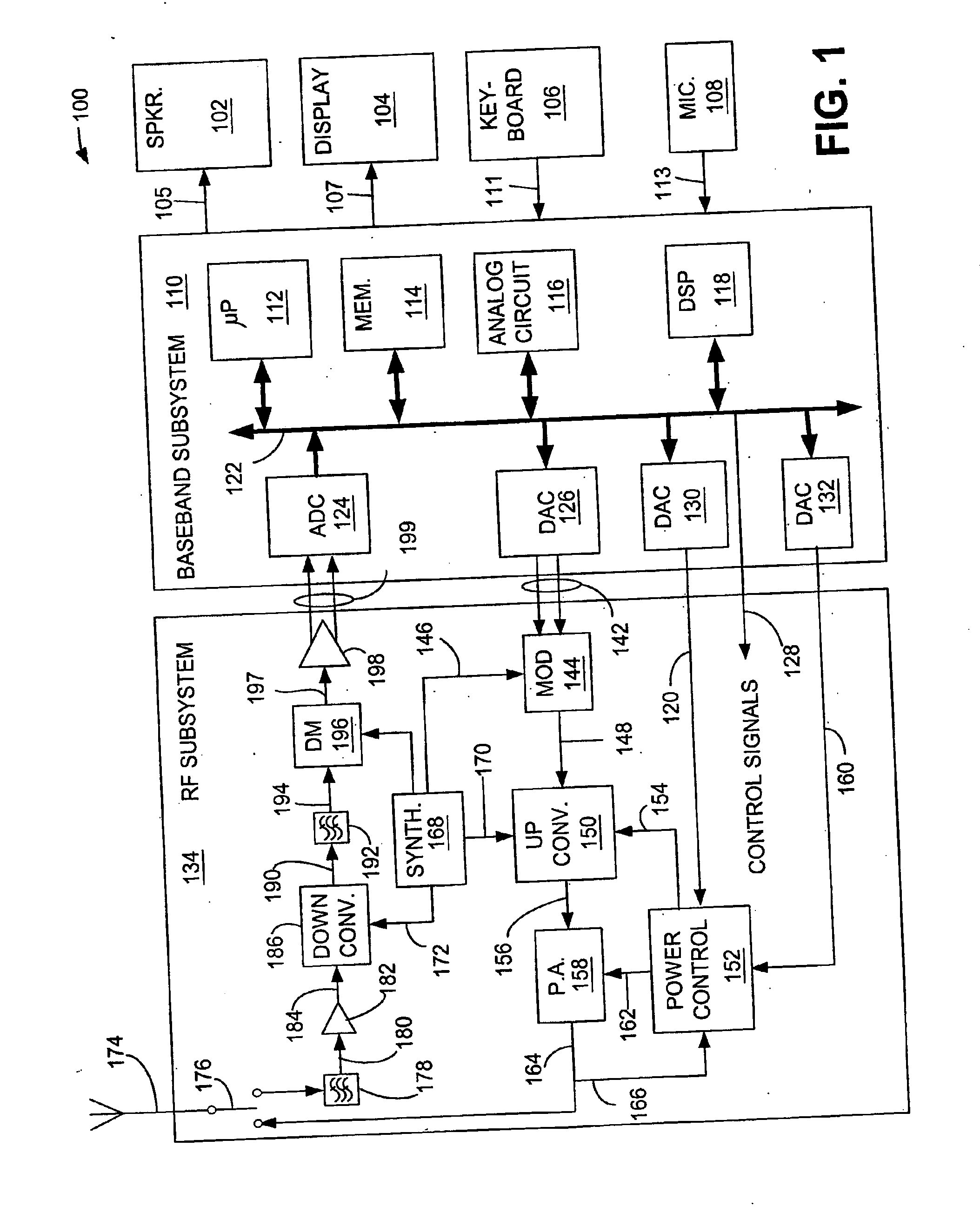
[0024]FIG. 1 is a block diagram illustrating a non-limiting example of a simplified portable transceiver 100 in which an embodiment of the invention may be implemented. Portable transceiver 100 includes speaker 102, display 104, keyboard 106, and microphone 108, all connected to baseband subsystem 110. In a particular embodiment, portable transceiver 100 can be, for example, but not limited to, a portable telecommunication handset such as a mobile cellular-type telephone. Speaker 102 and display 104 receive signals from baseband subsystem 110 via connections 105 and 107, respectively. Similarly, keyboard 106 and microphone 108 supply signals to baseband subsystem 110 via connections 111 and 113, respectively. Baseband subsystem 110 includes microprocessor (μP) 112, memory 114, analog circuitry 116, and digital signal processor (DSP) 118, each coupled to a data bus 122. Examples of commercially available processors include, but are not limited to, an ARM processor such as an ARM 7 or...


PUM


Abstract

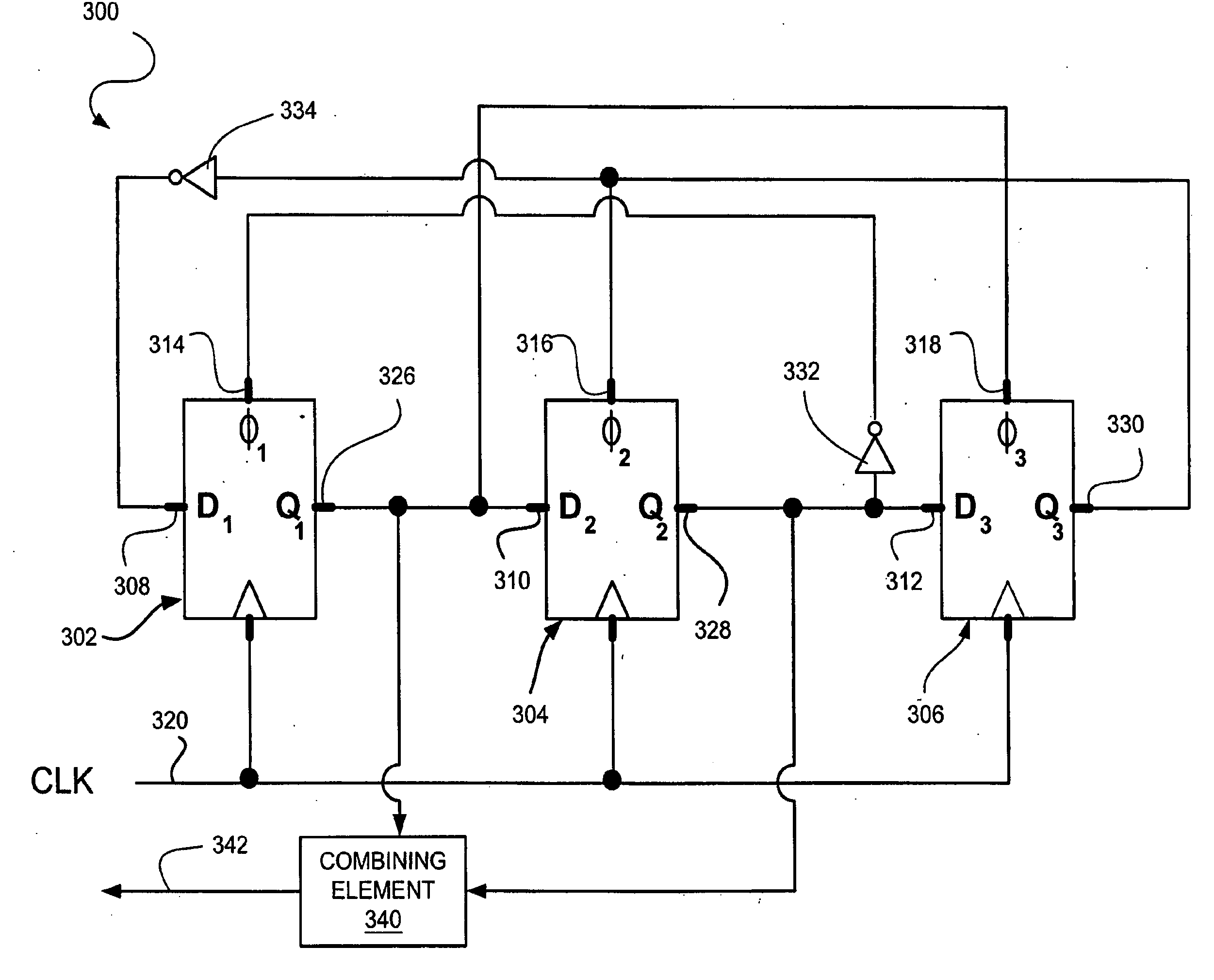
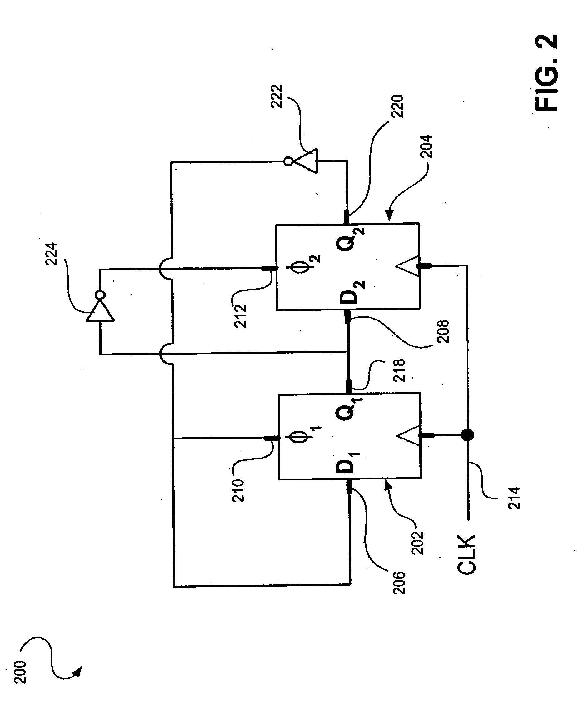
Systems and methods for producing a frequency divider output signal having a period substantially equal to three times a period of a reference input signal, comprising configuring each of three storage elements to receive a first input, a second input, and a reference input signal, and to provide a storage element output, obtaining a frequency divider output signal from at least one storage element output, and using the storage element output from each of the three storage elements as an input to another one of the three storage elements, where a phase difference between the output of the first storage element and the output of the second storage element is substantially equal to 60°.

Description

CLAIM OF PRIORITY [0001] This application is a continuation of copending U.S. utility application entitled, “Frequency Divider with Low Harmonics,” having Ser. No. 09 / 821,833, filed on Mar. 30, 2001, which is a continuation-in-part of copending U.S. utility application entitled “Programmable Frequency Divider,” Ser. No. 09 / 370,099, filed on Aug. 6, 1999, both of which are incorporated by reference in their entirety.BACKGROUND OF THE INVENTION [0002] 1. Field of the Invention [0003] This invention relates to wireless transmitters and receivers and, more particularly, to frequency dividers. [0004] 2. Related Art [0005] Harmonics contained in signal processing devices are a major cause of signal distortions. One case where harmonics can be especially problematic is in a limiter that is driven by a poly-phase filter. For example, standard 90° poly-phase outputs take the form of:0° output=input / (1+jwRC)90° output=input*(jwRC) / (1+jwRC) Based on this property, harmonic components in the ou...

Claims


Application Information

Patent Timeline
Patent Type & Authority Applications(United States)
IPC IPC(8): H03K21/00H03K21/10H03K23/66
CPCG06F7/68H03K21/08H03K23/667H03K23/544H03K21/10
Inventor MOLNAR, ALYOSHA C.MAGOON, RAHUL
Owner CONEXANT SYST INC
Learn More