X-ray ct apparatus

a computed tomography and x-ray technology, applied in tomography, instruments, applications, etc., can solve the problems of inability to adapt to the current value of the x-ray tube, and the above-ground x-ray automatic exposure function cannot fulfill the full function, so as to achieve the optimal image quality and improve the effect of image quality

Active Publication Date: 2007-12-13
GE MEDICAL SYST GLOBAL TECH CO LLC
View PDF22 Cites 30 Cited by
  • Summary
  • Abstract
  • Description
  • Claims
  • Application Information

AI Technical Summary

Benefits of technology

[0059]According to the X-ray CT apparatus of the present invention as well, priorities are assigned to plural parameters influencing each image and the plural parameters influencing the image are adjusted in order based on the priorities, thereby making it possible to efficiently realize the optimum image quality at an X-ray CT automatic exposure function as another effect.
[0060]That is, according to the present invention, an X-ray CT apparatus can be provided which is capable of improving image quality.

Problems solved by technology

Therefore, when an X-ray tube which is small in thermal capacity and needs to be cooled when a large X-ray tube current is outputted for long hours, or an X-ray tube which cannot output a large X-ray tube current, are mounted in the X-ray CT apparatus, there might be a case in which it is not possible to adapt to the set X-ray tube current values.
Thus, in such a case, there might be a case in which the above X-ray automatic exposure function cannot fulfill its full function.

Method used


Image

  • X-ray ct apparatus
  • X-ray ct apparatus
  • X-ray ct apparatus

Examples


first embodiment

[0085][Apparatus Configuration]

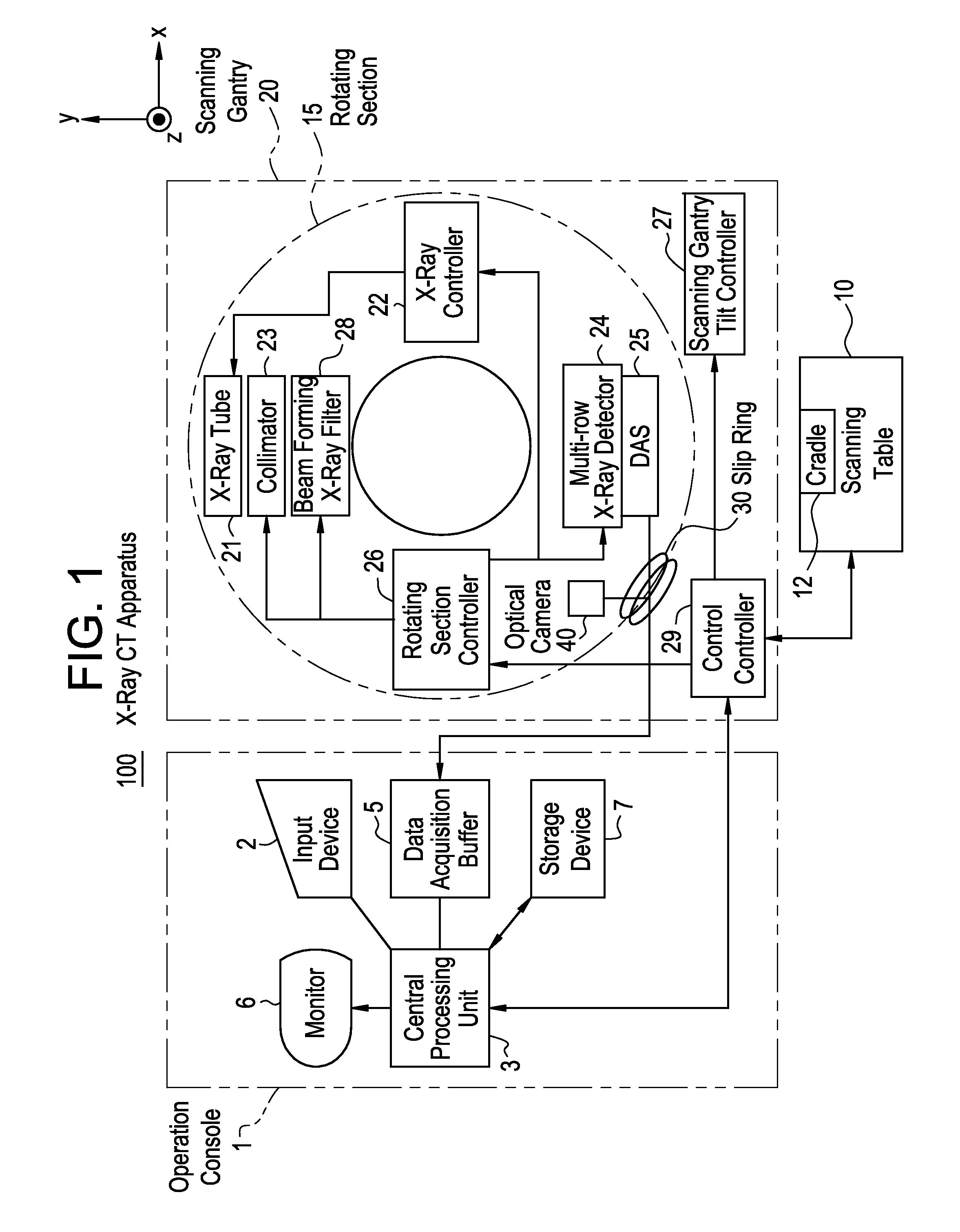
[0086]A configuration block diagram of an X-ray CT apparatus according to a first embodiment of the present invention is illustrated as shown in FIG. 1.

[0087]As shown in FIG. 1, the X-ray CT apparatus 100 according to the present embodiment is equipped with an operation console 1, an imaging or scanning table 10 and a scanning gantry 20.

[0088]As shown in FIG. 1, the operation console 1 includes an input device 2 which receives an input from an operator, a central processing unit 3 which executes data processing such as a pre-process, an image reconstructing process, a post-process, etc., a data acquisition buffer 5 which acquires or collects X-ray detector data acquired by the scanning gantry 20, a monitor 6 which displays a tomographic image image-reconstructed from projection data obtained by pre-processing the X-ray detector data, and a memory or storage device 7 which stores programs, X-ray detector data, projection data and X-ray tomographic image...

second embodiment

[0226]A second embodiment according to the present invention will be explained below.

[0227]The first embodiment shows the example in which the optimum image quality can be obtained by adjusting the helical pitch corresponding to one of parameters exerted on the image quality with respect to the range in which the set value of the X-ray tube current in the z-direction has exceeded the upper limit value, even when the set value of the X-ray tube current is set to within a range not greater than the upper limit value. On the other hand, the present embodiment shows an example in which even when a set value of an X-ray tube current is set to within a range not greater than an upper limit value, the optimum image quality can be obtained by adjusting channel direction filtering corresponding to one of parameters exerted on other image quality.

[0228]Except for this point, the present embodiment is similar to the first embodiment. Therefore, dual portions will not be explained.

[0229]FIG. 19...

third embodiment

[0237]A third embodiment according to the present invention will be explained below.

[0238]Each of the first and second embodiments has described where the image quality in the z-direction is optimized at the helical scan or the conventional scan (axial scan) or cine scan continuous in the z-direction.

[0239]In the present embodiment, each X-ray tube current is optimized in consideration of a helical pitch at a variable-pitch helical scan or a helical shuttle scan and changes in the number of rotations for projection data used in image reconstruction.

[0240]Except for this point, the present embodiment is similar to the first and second embodiments. Therefore, dual portions will not be explained.

[0241]FIGS. 20, 21 and 22 are respectively diagrams showing a relationship between a helical pitch, the number of rotations for used data and X-ray tube currents at a variable-pitch helical scan or a helical shuttle scan.

[0242]As shown in FIGS. 20, 21 and 22, the helical pitch is changed in a z...


PUM

PropertyMeasurementUnit
view anglesaaaaaaaaaa
view angleaaaaaaaaaa
view anglesaaaaaaaaaa

Abstract

The present invention aims to obtain a tomographic image similar in image quality to a tomographic image obtained by executing a scan at X-ray tube current value set by an X-ray automatic exposure function even when the X-ray tube current value set by the X-ray automatic exposure function are not within a standard range of the X-ray tube current values settable at the X-ray tube (21). X-ray tube current value supplied to the X-ray tube (21) are set by the X-ray automatic exposure function. Thereafter, when the X-ray tube current value set by the X-ray automatic exposure function is not within in the standard range of the X-ray tube current value settable at the X-ray tube, the X-ray tube current value at a portion not within the standard range are changed so as to be within the standard range, and the set value of helical pitch is changed so as to correspond to the ratio between the pre-changed x-ray tube current value and the post-changed X-ray tube current value.

Description

CROSS REFERENCE TO RELATED APPLICATIONS[0001]This application claims the benefit of Japanese Patent Application No. 2006-161245 filed Jun. 9, 2006.BACKGROUND OF THE INVENTION[0002]The present invention relates to a medical X-ray CT (Computed Tomography) apparatus, and to an X-ray CT apparatus which realizes a reduction in exposure and an improvement in image quality using an X-ray automatic exposure function upon a conventional scan (axial scan), a cine scan, a helical scan, a parameter-pitch helical scan or a helical shuttle scan.[0003]An X-ray CT apparatus having a multi-row X-ray detector or a two-dimensional X-ray area detector of a matrix structure typified by a flat panel has heretofore realized a reduction in exposure and an improvement in image quality using an X-ray automatic exposure function (corresponding to a function called “auto milliampere” or the like) (refer to, for example, Japanese Unexamined Patent Publication No. 2001-178713).[0004]Here, the term “X-ray automat...

Claims


Application Information

Patent Timeline
Patent Type & Authority Applications(United States)
IPC IPC(8): A61B6/00G01N23/00G21K1/12H05G1/60
CPCA61B6/032A61B6/488A61B6/027H05G1/30A61B6/542
Inventor GOHNO, MAKOTOHORIUCHI, TETSUYANISHIDE, AKIHIKOHAGIWARA, AKIRA
Owner GE MEDICAL SYST GLOBAL TECH CO LLC
Why Eureka
Try Eureka