Lamp fixing unit, backlight assembly having the same and display device having the same

a technology of backlight assembly and fixing unit, which is applied in the direction of coupling device connection, lighting and heating apparatus, instruments, etc., can solve the problems of troublesome manufacturing process and backlight assembly repair, and achieve the effect of easy coupling and uncoupling

Inactive Publication Date: 2007-12-13
SAMSUNG DISPLAY CO LTD
View PDF5 Cites 25 Cited by
  • Summary
  • Abstract
  • Description
  • Claims
  • Application Information

AI Technical Summary

Benefits of technology

[0017]According to the above, the power supply terminals of the power supply member are electrically connected to the first connection portion through the first and second openings, so that the power supply member is easily coupled to and uncoupled from the lamp holders. Also, the array plate including metal is coupled to the receiving container, and the ground lead and the array plate are electrically connected through the conductive socket of the first lamp holders, thereby easily coupling the ground lead to the receiving container (i.e., grounding the ground lead).

Problems solved by technology

The above-mentioned manual procedures make both the manufacturing process and the repair of the backlight assembly troublesome.

Method used


Image

  • Lamp fixing unit, backlight assembly having the same and display device having the same
  • Lamp fixing unit, backlight assembly having the same and display device having the same
  • Lamp fixing unit, backlight assembly having the same and display device having the same

Examples


Embodiment Construction

[0045]The present invention now will be described more fully hereinafter with reference to the accompanying drawings, in which embodiments of the invention are shown. This invention may, however, be embodied in many different forms and should not be construed as limited to the embodiments set forth herein; rather, these embodiments are provided so that this disclosure will be thorough and complete, and will fully convey the scope of the invention to those skilled in the art. It will be understood that when an element is referred to as being “on” or “onto” another element, it may be directly on the other element or intervening elements may also be present.

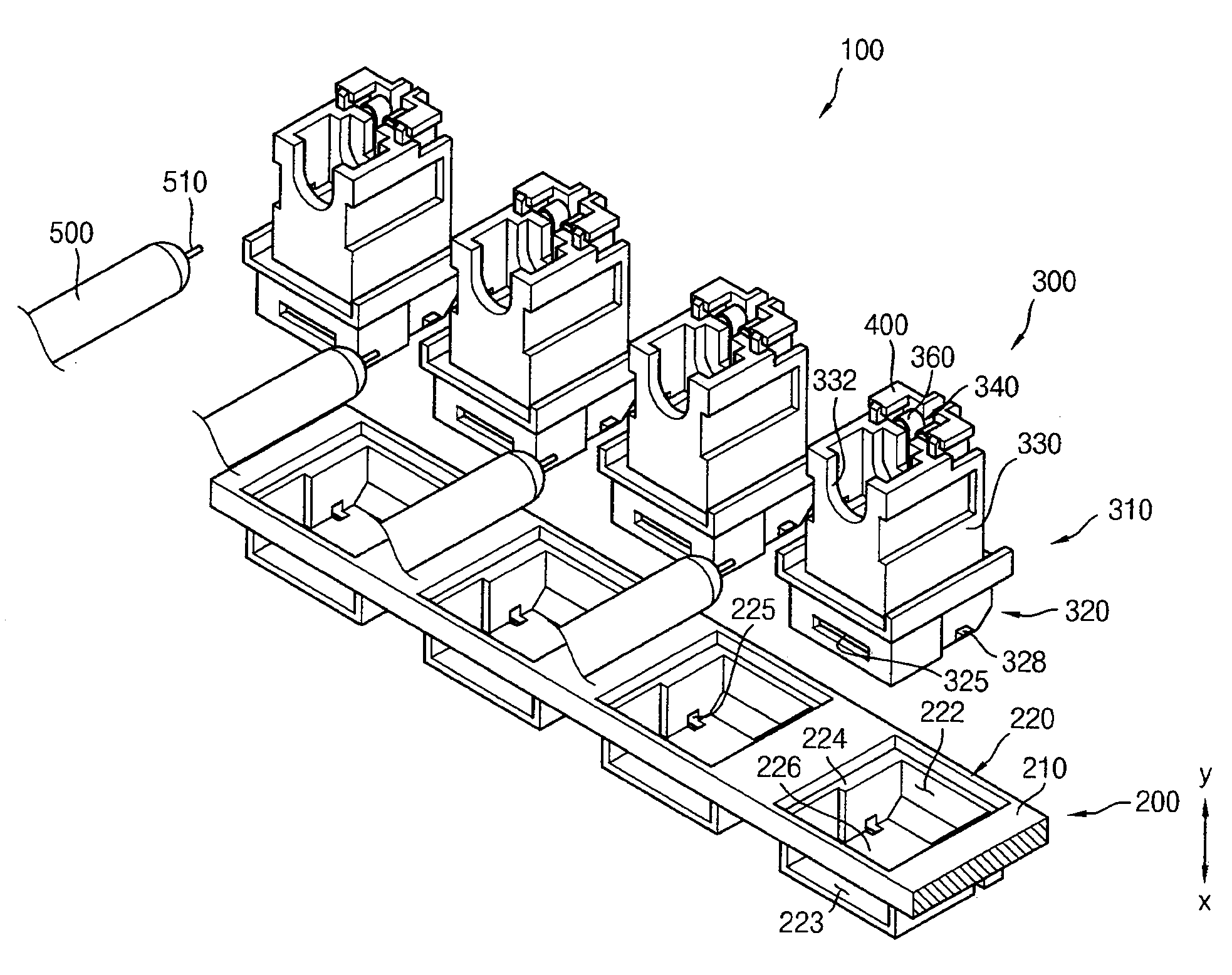
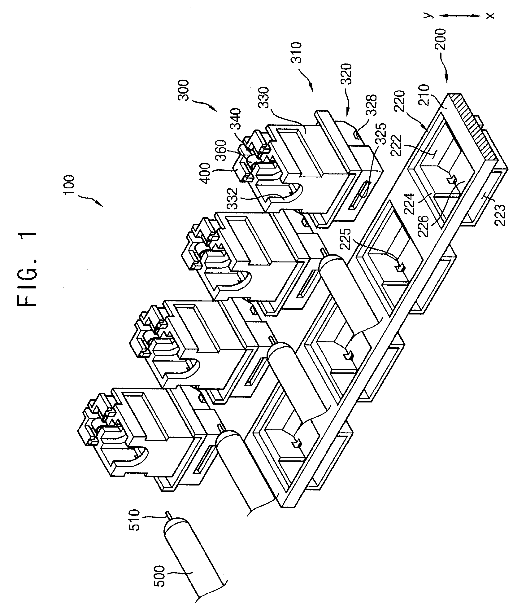
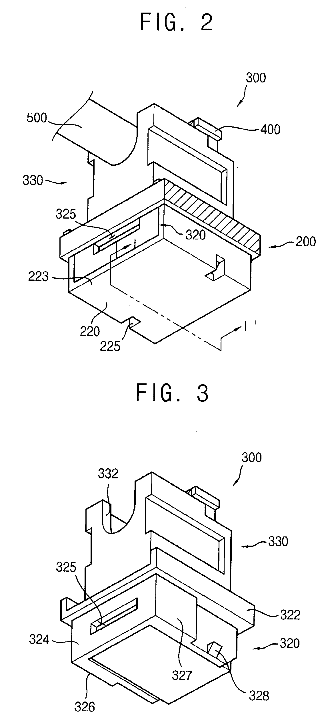
[0046]FIG. 1 is an exploded perspective view illustrating a lamp fixing unit according to an exemplary embodiment of the present invention. FIG. 2 is a rear perspective view illustrating the lamp-fixing unit illustrated in FIG. 1. FIG. 3 is a perspective view illustrating the lamp holder illustrated in FIG. 2.

[0047]Referring to FIGS...


PUM


Abstract

A lamp fixing unit capable of simplifying the manufacture of a backlight assembly by eliminating the need for manual procedures is presented. The lamp fixing unit includes a fixing member and a lamp holder. The fixing member includes a fixing body and at least one receiving portion. The lamp holder includes a holder body and a conductive socket. The holder body includes a board insertion portion, a power supply member, and a lamp fixing member. Thus, the power supply member may be easily coupled to and uncoupled from the lamp holder, and the lamp may be easily grounded.

Description

CROSS-REFERENCE TO RELATED APPLICATIONS[0001]This application relies for priority upon Korean Patent Application No. 2006-45972 filed on May 23, 2006 and Korean Patent Application No. 200649222 filed on Jun. 1, 2006, the contents of which are herein incorporated by reference in their entireties.BACKGROUND OF THE INVENTION[0002]1. Field of the Invention[0003]The present invention relates to a lamp fixing unit, a backlight assembly having the lamp fixing unit and a liquid crystal display device having the lamp fixing unit. More particularly, the present invention relates to a lamp fixing unit capable of easily coupling and uncoupling a lamp holder and a power supply member, and easily grounding a lamp, a backlight assembly having the lamp fixing unit and a liquid crystal display device having the lamp fixing unit.[0004]2. Description of the Related Art[0005]Generally, a liquid crystal display (LCD) device includes an LCD panel displaying an image and a backlight assembly providing lig...

Claims


Application Information

Patent Timeline
Patent Type & Authority Applications(United States)
IPC IPC(8): G03G15/20
CPCF21V19/0085G02F1/133308H01R33/02G02F1/133608H01R31/085G02F1/133604
Inventor KWON, YOON-SOOKANG, JUNG-TAEHA, JIN-HOWON, JOO-YEONYANG, YONG-SEOK
Owner SAMSUNG DISPLAY CO LTD
Why Eureka
Try Eureka