Variable input radiant heater

a radiant heater and variable input technology, applied in the direction of heating types, combustion types, combustion failure safes, etc., can solve the problems of regulating the excess air percentage, complex detection and control systems, and prohibitively expensive in many applications,

Inactive Publication Date: 2007-12-13
ROBERTS GORDON INC
View PDF36 Cites 13 Cited by
  • Summary
  • Abstract
  • Description
  • Claims
  • Application Information

AI Technical Summary

Problems solved by technology

Those alternative methods are, according to Ripka et al., impractical.
In particular Ripka et al. wrote, “While it is possible to directly measure the flow ratio of the fuel gas and air supplies to a burner and to regulate one or both of the flows so as to produce a combustible gas mixture that is optimum, such a detection and control system would be complex and prohibitively expensive in many applications.
The designs of some burner applications include pressure switches to detect air flow rate, but such switches are capable only of detecting gross departures from the optimum excess air value and not of regulating the excess air percentage.
Those designs however are subject to sensor fouling and can be unreliable and inaccurate.” In other words, Ripka et al. clearly and unequivocally teaches (1) measuring flow ratios of fuel and air is possible but too expensive to be used for radiant burner devices, (2) measuring the pressure of the air, not fuel, through pressure switches but those pressure switches are unreliable, and (3) measuring the concentration of certain gases emitted from the flame.
The dual regulation is limited to only providing a high or low input rate to respond to a high or low heat demand.
Such two-stage burners are limited to only two distinct operating rates offering only coarse control of varying demands and do not match the heat demand for the majority of the time.
In both patents mentioned (U.S. Pat. No. 5,353,986 and U.S. Pat. No. 5,989,011), there are disadvantages to varying gas volume (or pressure) to the burner mixing apparatus without also varying combustion air volume (or pressure) to the burner's mixing means.
Seel does not disclose, teach or suggest any ability to control a single “unitary” style infrared heater with associated burner modulating controls and blower mounted internal to the burner housing.
Fractional horsepower DC motors are readily available in the market and can easily be controlled to vary their speed, but a DC motor is more expensive than a shaded pole motor of similar size.
In addition to the DC motor costing more, a controller is needed to send a control signal to the DC motor to vary its speed; a controller would also need to send a separate control signal to vary the gas valve, adding more cost.
That capability is not possible in current modulating or two stage infrared heater design with single speed blowers.

Method used


Image

  • Variable input radiant heater
  • Variable input radiant heater
  • Variable input radiant heater

Examples


Embodiment Construction

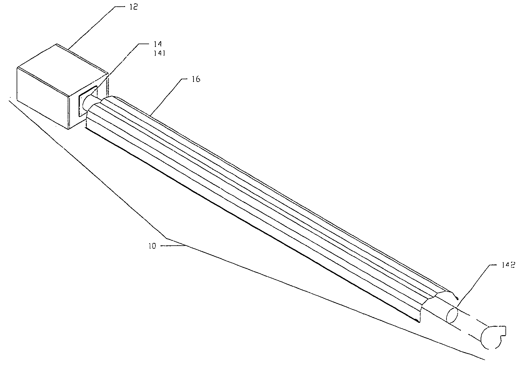
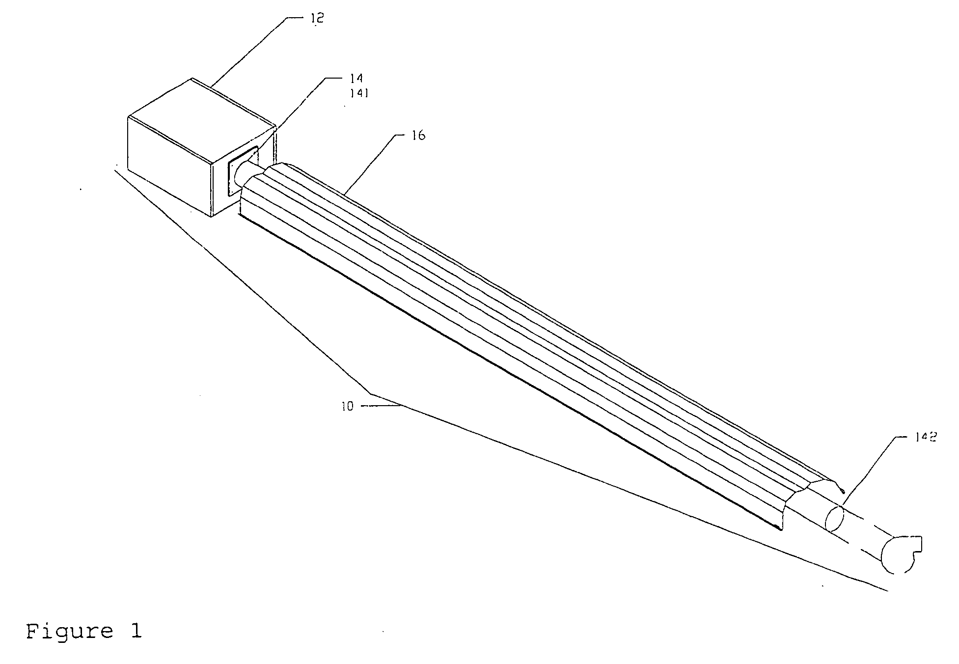
[0024] Generically, the present invention is directed to a single radiant heater or multi-burner radiant heating system. In particular, the present invention is directed to a single radiant heater or multi-burner radiant heating system that modulates the burner input by varying fuel and combustion air supply to the burner's mixing apparatus. The apparatus continuously varies the input of radiant gas heaters that respond to heat demand. The variable input radiant heater apparatus have a burner housing with a combustion air and fuel inlet and a burner assembly for mixing the fuel and air, and conveying the mixture into a heat exchanger for combustion. Combustion takes place inside the heat exchanger and resulting hot products of combustion are moved to through the heat exchanger to the exhaust end due to air pressure from a combustion air blower providing either positive air pressure from the burner end of the heater or negative pressure from the exhaust end of the heater. At the exha...


PUM


Abstract

A variable demand radiant heating system applies variable burner control technology to singular or multi-burner radiant heating systems. A radiant heater consists of a burner connected to an elongated heat exchanger tube. The combustion air is supplied to the burner via blower or draft inducer. Fuel is supplied to the burner via fuel regulator. Fuel and air are mixed in burner and communicated to the inlet end of the heat exchanger tube. Spent products of combustion are expelled from the heat exchanger at the outlet end. The burner controls continuously vary gas supply pressure (volume), via a modulating gas regulator, and combustion air pressure (volume), via a variable speed blower, communicated to the burner mixing chamber, which in turn, varies the burner input on a continuous curve (not stepped or staged) within a pre-determined input range as heat demand varies.

Description

CLAIM OF PRIORITY [0001] This application claims priority as a continuation-in-part application to U.S. patent application Ser. No. 10 / 858,244, filed on Jun. 1, 2004.FIELD OF THE INVENTION [0002] The present invention relates controlling the thermal energy generated by a heating system. BACKGROUND OF THE INVENTION [0003] In U.S. Pat. No. 5,112,217, Ripka et al. describe a radiant burner having (1) a constant flow of fuel, (2) a variable flow of air, (3) an ignition source, (4) a radiation sensor that measures the radiation or luminosity of the flame and transmits that measurement to a computer, and (5) the computer computes what the desired efficiency should be and transmits signals to the variable flow of air apparatus to control the amount of air that enters the radiant burner to obtain the alleged maximum flame efficiency. [0004] In particular, Ripka et al. describe the control system as controlling the fuel-to air ratio by varying combustion air to the burner; controlling fuel g...

Claims


Application Information

Patent Timeline
Patent Type & Authority Applications(United States)
IPC IPC(8): F23N1/00F24H3/00F23D14/12F23N1/02F23N5/18F23N5/24F24D5/08
CPCF23D14/12F23N1/022F23N5/184F23N5/242F24D5/08F23N2027/04F23N2031/26F23N2033/08F23N2033/10F23N2025/04F24H9/2035F23N2227/04F23N2231/26F23N2233/10F23N2225/04F23N2233/08F23D14/151F23K5/002F24H3/00F24H15/242F24H15/20F24H15/31F24H15/36F24H15/35
Inventor STONE, PATRICK C.MURDOCH, MARK V.
Owner ROBERTS GORDON INC
Why Eureka
Try Eureka