
Adaptive wireless receiver

a wireless receiver and receiver technology, applied in the direction of transmission, electrical equipment, etc., can solve the problems of limiting the performance of the receiver system, affecting the performance of increasing the complexity and cost of the integrated circuit where the zif wireless receiver b>200/b> is embedded,

Active Publication Date: 2007-12-13
O2 MICRO INT LTD
View PDF2 Cites 21 Cited by
  • Summary
  • Abstract
  • Description
  • Claims
  • Application Information

AI Technical Summary

Benefits of technology

[0011]In one embodiment, there is disclosed an adaptive receiver for processing a radio frequency (RF) signal to support multiple standards. The receiver includes an antenna, a bandpass filter (BPF), a front-end unit, and a demodulator. The antenna receives the RF signal. The BPF filters the RF signal. The front-end unit processes the filtered signal from the BPF and generates digitalized signals. The demodulator demodulates the digitalized signals. The front-end unit executes channel selection when the adaptive wireless receiver operates in a zero intermediate frequency (ZIF) mode and executes image rejection when the adaptive wireless receiver operates in a low intermediate frequency (LIF) mode.
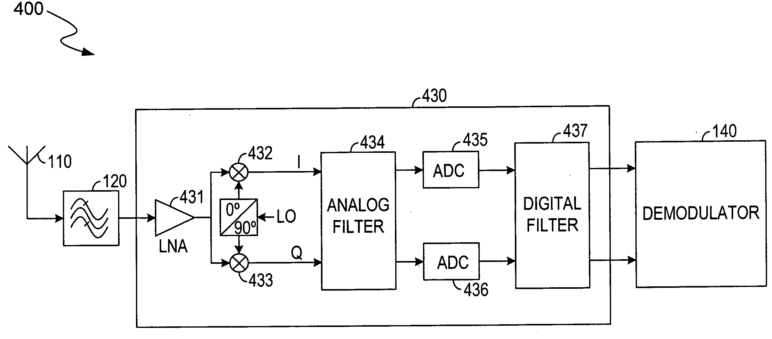
[0012]In one embodiment, there is disclosed an apparatus for converting a bandpassed (BP) radio frequency (RF) signal to a desired intermediate frequency (IF) signal. The apparatus includes a low noise amplifier (LNA), a first and second mixer, an analog filter, a first and second analog-to-digital converter (ADC), and a digital filter. The LNA amplifies the BP RF signal and generates an amplified RF signal. The first mixer converts the amplified RF signal from RF to IF and generates an in-phase (I) signal. The second mixer converts the amplified RF signal from RF to IF and generates a quadrature-phase (Q) signal. The analog filter filters the I and Q signals. The first and second ADCs convert the filtered I and Q signals from analog to digital. The digital filter filters the digitalized I and Q signals.
[0013]In another embodiment, there is disclosed a method for converting a radio frequency (RF) signal to an intermediate frequency (IF) signal by a receiver. The method includes the steps of (a) filtering the RF signal with a frequency band, (b) amplifying the filtered RF signal, (c) down-converting the amplified RF signal to an IF signal including an in-phase (I) signal and a quadrature-phase (Q) signal when the receiver operates in a zero intermediate frequency (ZIF) mode and in a low intermediate frequency (LIF) mode, (d) filtering the IF signal, (e) converting the filtered IF signal to a digital signal including a digitalized I signal and a digitalized Q signal, and (f) filtering the digital signal.

Problems solved by technology

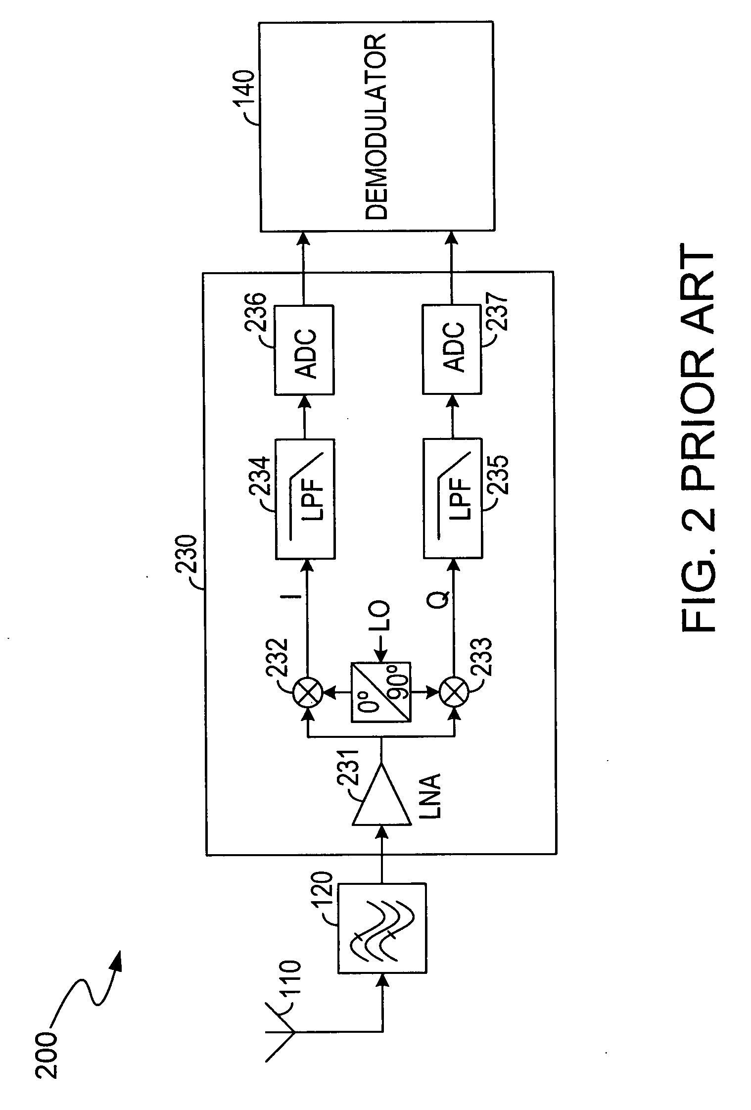
As a result, the complexity and cost of the integrated circuit where the ZIF wireless receiver 200 is embedded will be greatly increased.
In addition, the mismatch between the I path and the Q path and a DC offset caused by the mix between the RF signal and the LO signal can adversely affect the performance of the ZIF wireless receiver 200.
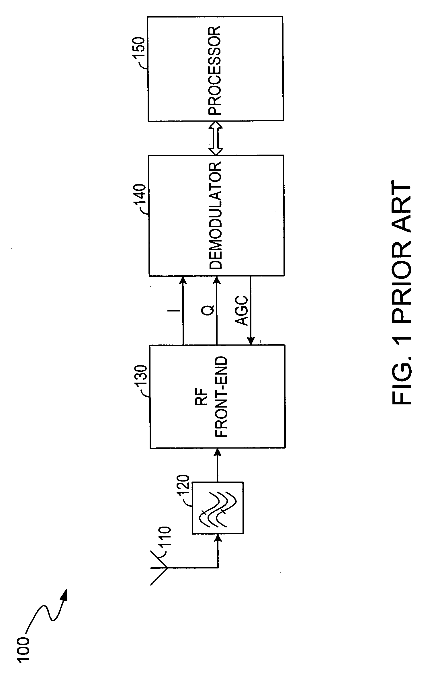
The main drawback for the LIF wireless receiver 300 is the low IRR (image rejection rate) caused by the mismatch between the I and Q paths, which greatly limits the performance of the receiver system.
However, because of the incompatibility between the ZIF and LIF topologies, more tuners are required to support these different standards in traditional solutions.
Furthermore, the reuse of hardware is very limited in the traditional solutions.
Hence, the performance of the receiver system is limited and the silicon area of the integrated circuit will be significantly expanded when both topologies are included.

Method used


Image

  • Adaptive wireless receiver
  • Adaptive wireless receiver
  • Adaptive wireless receiver

Examples


Embodiment Construction

[0020]FIG. 4 illustrates a simplified block diagram of an adaptive wireless receiver 400 according to the present invention. Because the adaptive wireless receiver 400 is similar to the ZIF (zero intermediate frequency) wireless receiver 200 and the LIF (low intermediate frequency) wireless receiver 300, the similar components thereof are indicated by similar symbols for clarity. The adaptive wireless receiver 400 described in details below can operate in both ZIF mode and LIF mode. The adaptive wireless receiver 400 is configured to support multiple standards and different frequency bands. The adaptive wireless receiver 400 includes the antenna 110, the bandpass filter (BPF) 120, a RF front-end unit 430 and the modulator 140. The RF front-end unit 430 includes a LNA (low noise amplifier) 431, down-conversion mixers 432 and 433, an analog filter 434, ADCs (analog-to-digital converters) 435 and 436, and a digital filter 437.

[0021]The antenna 110 is used to receive the RF signal from ...


PUM


Abstract

An adaptive wireless receiver and method thereof is disclosed in the present invention. The receiver includes an antenna, a bandpass filter, a front-end unit and a demodulator. Elements inside the front-end unit can be reused when the receiver operates in a zero intermediate frequency (ZIF) mode and in a low intermediate frequency (LIF) mode. The front-end unit includes a first and second down-conversion mixer, an analog filter, a first and second analog-to-digital converter (ADC), and a digital filter.

Description

RELATED APPLICATION[0001]This application claims the benefit of U.S. provisional application, titled Adaptive Wireless Receiver, Ser. No. 60 / 811,902, filed on Jun. 8, 2006, the specification of which is incorporated herein in its entirety by this reference.BACKGROUND OF THE INVENTION[0002]1. Field of the Invention[0003]The present invention relates to wireless communication systems and in particular to an adaptive wireless receiver that supports multiple standards and / or multiple frequency bands.[0004]2. Description of the Related Art[0005]Currently, the increase demand for wireless communication systems has resulted in continuing development of wireless receivers. The receivers are commonly employed in radio frequency (RF) signal transmission. In the wireless communication field, the receivers usually are capable of receiving RF signals through an antenna. The receivers convert these RF signals to desirable intermediate frequency (IF) signals before they are converted to a baseband...

Claims


Application Information

Patent Timeline
Patent Type & Authority Applications(United States)
IPC IPC(8): H04B1/26H04B1/16
CPCH04B1/406H04B1/0003
Inventor FENG, DONGCHEN, JIWEI
Owner O2 MICRO INT LTD
Learn More