
Vehicle steering system

a steering system and vehicle technology, applied in the direction of steering initiation, distance measurement, instruments, etc., can solve the problems of affecting the use of automatic parking control, the interference of the steering force input by the driver and the torque generated by the automatic parking control, etc., to achieve smooth movement and facilitate use.

Active Publication Date: 2007-12-13
JTEKT CORP
View PDF8 Cites 25 Cited by
  • Summary
  • Abstract
  • Description
  • Claims
  • Application Information

AI Technical Summary

Benefits of technology

[0009]Then, an object of the invention is to provide a vehicle steering system which enables the driver to smoothly move on to a driving operation subsequent to the application of the brake, so as to make the automatic steering function easy to be used.
[0018]According to the configuration that has been described above, the automatic steering control is cancelled in no case within a range where the manipulation urgency of the brake application member does not exceed the predetermined threshold value. In addition, since the automatic steering control is cancelled when the manipulation urgency of the brake application member exceeds the threshold value, the interference between the driving operation which the driver is to perform subsequently and the automatic steering control can be suppressed or prevented, the smooth shift to the driving operation subsequent to the application of the brake is enabled. In addition, when the predetermined control resuming condition is established, the automatic steering control can be resumed using the control resumption data without requiring a resetting operation by the driver. Thus, the automatic steering system which is improved in handling can be realized in the way described above.
[0020]According to the configuration that has been described above, the automatic steering control can be resumed by canceling the application of the brake without involving the steering operation or gearshift operation. In addition, when the steering operation or gearshift operation is performed before the application of the brake is cancelled, since the automatic steering control has already been cancelled then, the steering operation or gearshift operation interferes in no case with the automatic steering control. Consequently, a smooth shift to the steering operation or gearshift operation is enabled after emergency braking during the automatic steering control.

Problems solved by technology

However, in the case that the driver stops manipulating the brake application device in order to cancel the automatic parking control after the driver found the obstacle in the traveling direction of the vehicle and has stopped the vehicle, there exists a fear that the vehicle continues to move towards the obstacle due to the creeping force and then eventually comes into contact with the obstacle.
In addition, since the automatic parking control has not yet been cancelled in such a state that the vehicle is stopped while keeping the brake application device manipulated, when the driver attempts to avoid the obstacle by manipulating the steering wheel, the steering force inputted by the driver and the torque generated as a result of the automatic parking control are caused to interfere with each other.
Because of this, the driver cannot smoothly move on to a subsequent driving operation after the driver has stopped the vehicle.
However, the system cannot be applied to the automatic parking control in which the application of the brake is inevitable.
Consequently, once the brake is applied, the operation process for resuming the cancelled automatic parking control becomes complicated and troublesome.
Therefore, the disclosed system cannot be put into practical use for the automatic parking control.
In this way, the conventional automatic steering function such as the automatic parking has the drawback that the driver cannot smoothly move on to a driving operation subsequent to the application of the brake, and this function is not necessarily easy for the driver to use.

Method used


Image

  • Vehicle steering system
  • Vehicle steering system
  • Vehicle steering system

Examples


Embodiment Construction

[0026]Hereinafter, embodiments of the invention will be described in detail by reference the accompanying drawings.

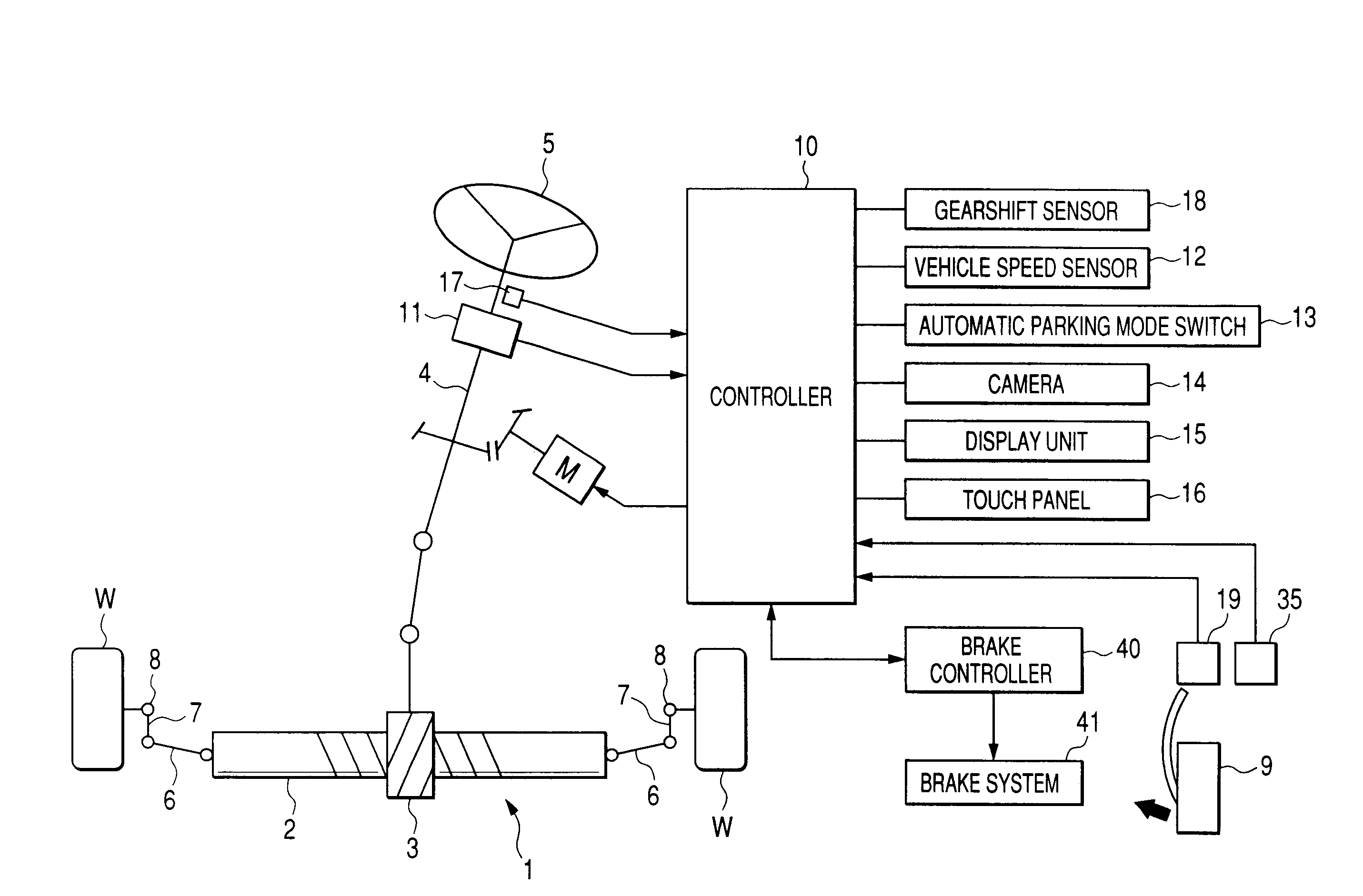
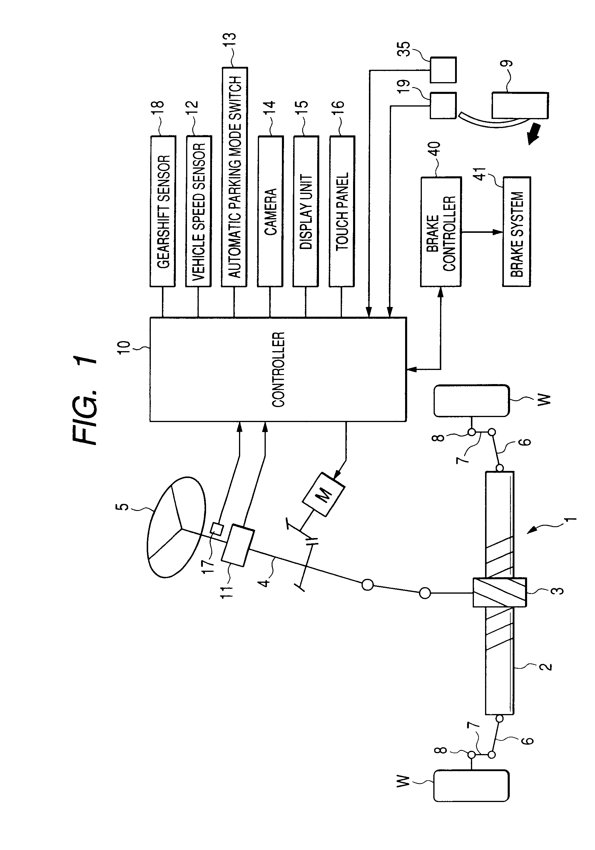
[0027]FIG. 1 is a conceptual diagram which describes the configuration of an electric power steering system as a vehicle steering system according to an embodiment of of the invention. The electric power steering system is configured such that torque generated by an electric motor M functioning as a steering actuator is transmitted to a steering mechanism 1 for turning steered road wheels W (for example, left and right front road wheels) of a vehicle. The steering mechanism 1 is a rack-and-pinion type steering mechanism which includes a rack shaft 2 which extends along a lateral direction of the vehicle and a pinion 3 which meshes with a gear portion of the rack shaft 2. One end of a steering shaft 4 is connected to the pinion 3, while a steering wheel 5 functioning as a control member is connected to the other end of the steering shaft 4. Consequently, when the steerin...


PUM


Abstract

A brake application speed is compared with a speed threshold value so as to judge whether or not a braking operation being performed is an emergency braking operation. If not the emergency braking operation, an automatic parking mode is held. When the emergency braking operation is in effect, control information related to a state of an automatic parking control then is stored in a control information storage section, and the automatic parking control is cancelled. Thereafter, when a steering operation or a gearshift operation is performed before a cancellation of application of the brake is detected, the process is ended, and the control mode is held in an assist mode. When the application of the brake is cancelled with neither the steering operation nor the gearshift operation performed, the control information is read in so as to resume the automatic parking control.

Description

[0001]This application is based on and claims a priority from a Japanese Patent Application No. 2006-163746 filed on Jun. 13, 2006, the entire contents of which are incorporated by reference.BACKGROUND OF THE INVENTION[0002]The present invention relates to a vehicle steering system which can perform an automatic steering control and cancel the control.[0003]There are proposed techniques for performing an automatic steering of a vehicle by making use of a steering actuator provided on the vehicle. For example, a power steering system installed on a vehicle includes an electric motor or a hydraulic actuator as a steering actuator for imparting a steering force (a steering assist force) to a steering mechanism. Then, steered road wheels of the vehicle can be turned by controlling the output of the steering actuator without involving the manipulation of a steering wheel by the driver.[0004]More specifically, in an automatic parking assist control, a target traveling path from a current ...

Claims


Application Information

Patent Timeline
Patent Type & Authority Applications(United States)
IPC IPC(8): B62D6/00
CPCB62D15/0285B60T2201/10
Inventor MAEDA, SHINGOARIMA, MASANORIMAEDA, NAOKIYAMANAKA, KOSUKEISHIHARA, ATSUSHIKOUCHI, TATSUMAMAEDA, DAISUKE
Owner JTEKT CORP
Learn More