
Loading Machine

Active Publication Date: 2007-12-20
J C BAMFORD EXCAVATORS LTD
View PDF14 Cites 5 Cited by
  • Summary
  • Abstract
  • Description
  • Claims
  • Application Information

AI Technical Summary

Benefits of technology

[0005] A loading machine in accordance with the invention may by virtue of the suspension and four wheel anti-locking brakes, safely travel at high speeds over the ground reducing the requirement for transporting the machine between work locations.
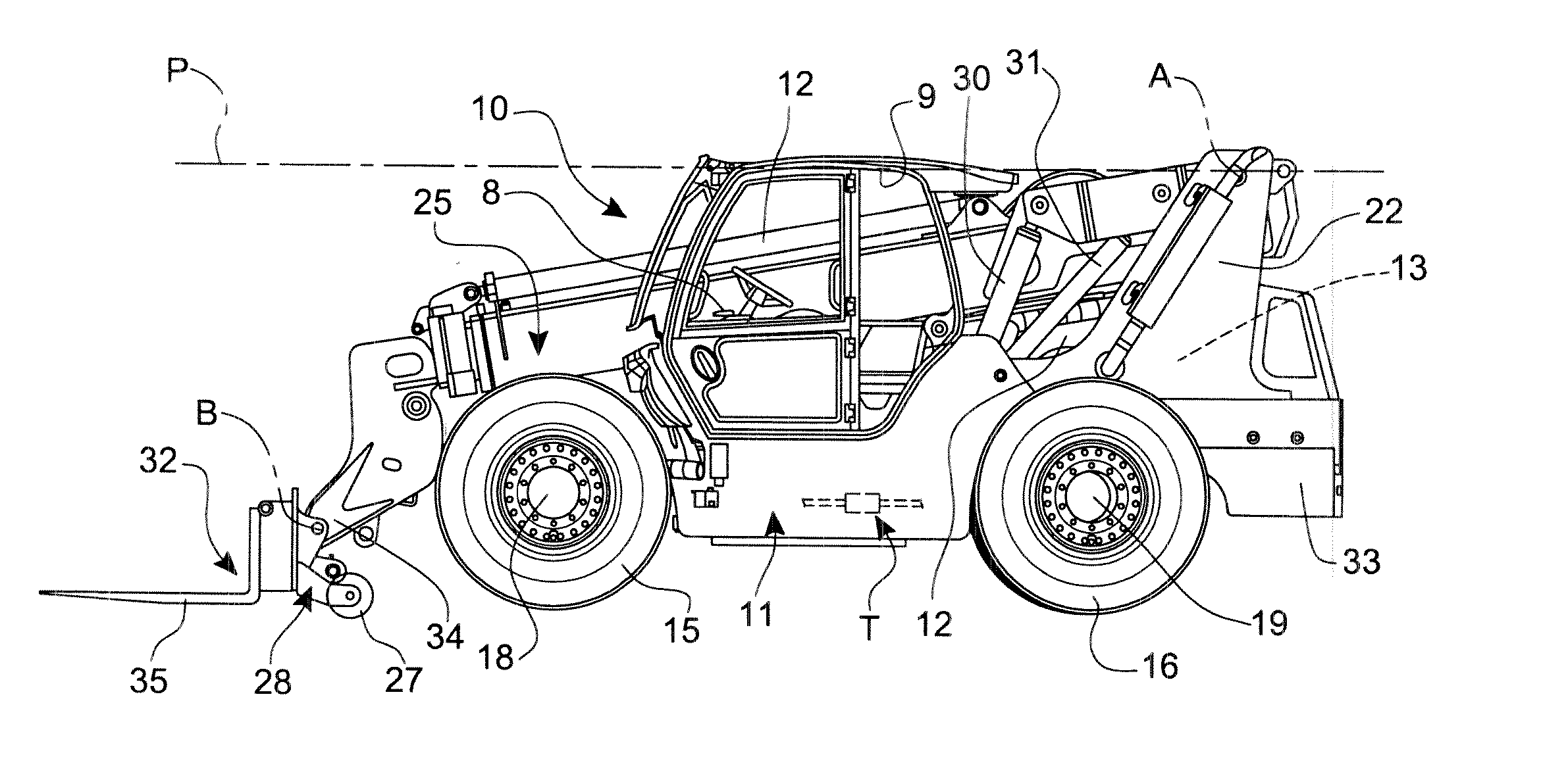
[0015] Desirably, to aid stability when the machine is performing loading operations, the body includes, at the rear end, a counterweight at a low position, which counterweight extends rearwardly of the body beyond the horizontal axis about which the loading arm is moveable. The loading arm may be mounted at a relatively high position. For example, the horizontal axis about which the loading arm is moveable may be located in a generally horizontal plane which contains or is spaced above or at least close to an upper level of the operator's cab. However, a lower mounting position may be provided if required.
[0016] Whereas the engine could be mounted by the body at a side of the body opposite to the position of the cab, preferably the engine is mounted by the body above the rear axle and below a rear portion of the loading arm, so as to provide some counterweighting during loading operations, and to minimise the body width.
[0017] When a loading implement is mounted at the outermost end of the loading arm, the loading implement may be a loading device such as a pair of forks, provided on a carriage which is mounted to the loading arm mounting. The carriage may include at least one wheel, which when the loading arm is in a lowered position, engages the ground. Particularly where the loading arm is extended to a great extent and the arm is in a lowered position, where maximum machine overturning forces are experienced, the provision of the at least one wheel on the carriage may enable the counterweight to be reduced, enabling the machine to be made lighter than otherwise, thereby enabling the machine to travel faster than a comparable machine without this carriage wheel feature.

Problems solved by technology

Such machines conventionally may only be driven over the ground at relatively slow speeds, for example around 30 km per hour.
Whereas this speed is adequate when such a machine is performing loading operations, it is overly slow for road travel, for example for moving the machine from one location to another.

Method used


Image

  • Loading Machine
  • Loading Machine
  • Loading Machine

Examples


Embodiment Construction

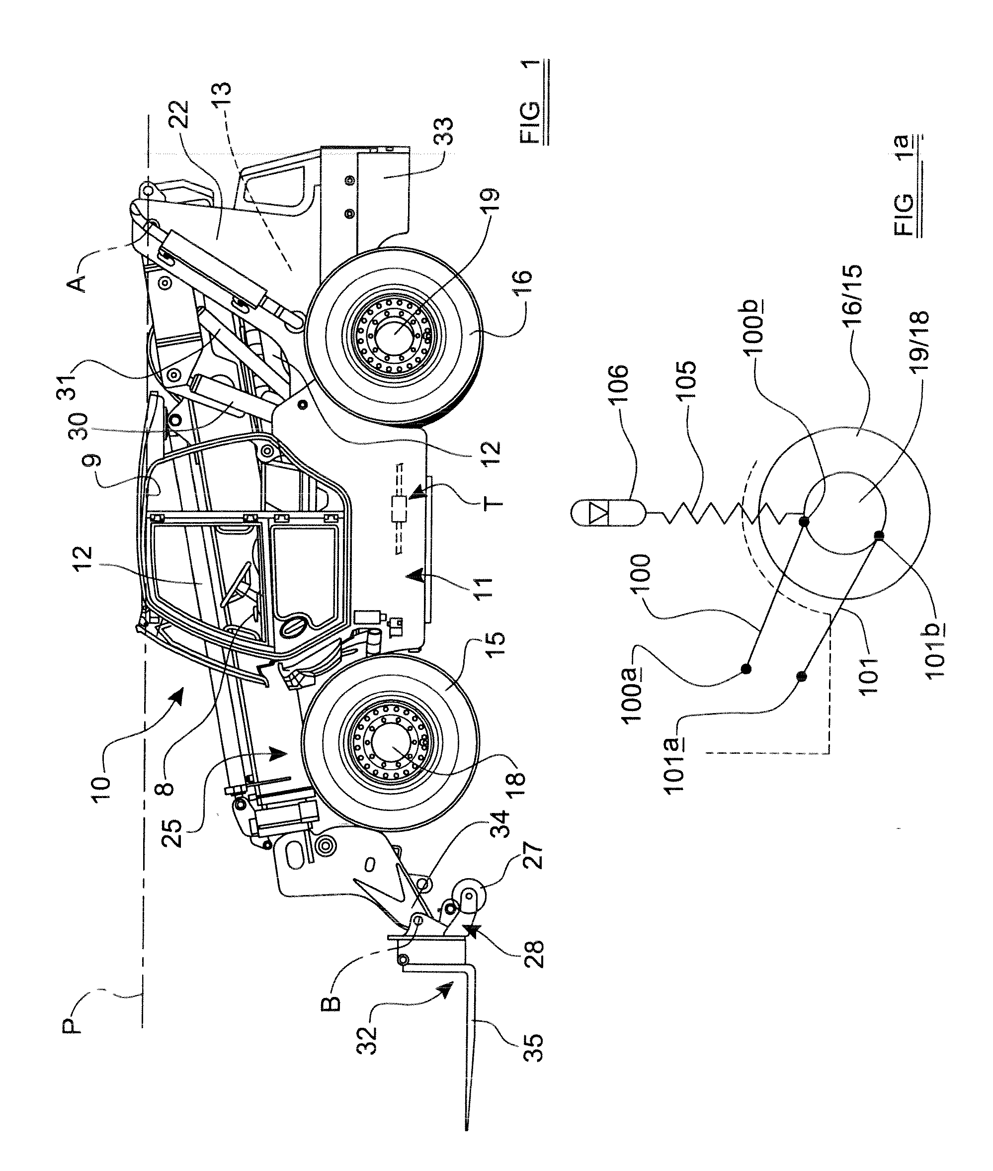
[0022] Referring to the drawings there is shown a loading machine 10 which includes a body 11 including a housing 12 for an engine which provides power for the machine 10. The position of the engine is indicated at 13 The machine 10 further includes a ground engaging structure including a front pair of wheels 15 and a rear pair of wheels 16, the front pair of wheels 15 being carried on a front axle 18 and the rear pair of wheels 16 being carried on a rear axle 19.

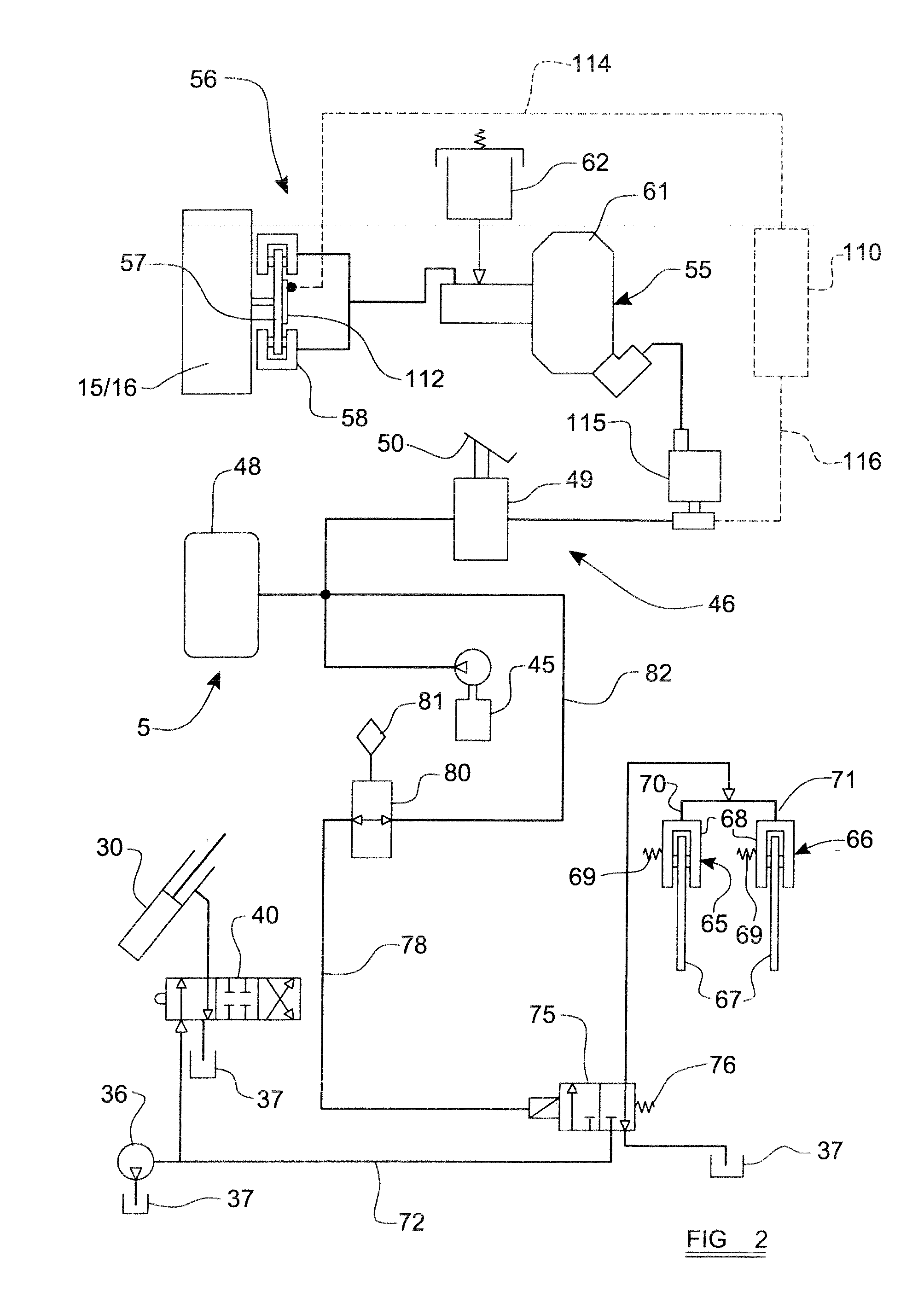
[0023] Both pairs of wheels 15, 16 in this example are driven wheels, being driven by their respective axles 18, 19 from respective transmission members (not seen) of a mechanical machine transmission T to which drive is provided from the engine 13. All four wheels 15, 16 are braked by a braking system 5 which is shown schematically in FIG. 2.

[0024] The body 11 of the loading machine 10 mounts the engine 13 at or towards a rear end thereof The body 11 also includes at or towards the rear end thereof, a tower mounting stru...


PUM


Abstract

A wheeled loading machine includes a body mounting a loading arm, a ground engaging structure including a front axle which carries a front pair of ground engaging wheels and a rear axle which carries a rear pair of ground engaging wheels, the loading arm being mounted at a position towards a rear of the machine for up and down movement about a generally horizontal axis, and the loading arm extending forwardly beside a cab which is mounted at one side of the body, to an outermost end which is beyond a front of the body, and the loading arm having at its outermost end a mounting for a loading implement and the arm being extendible to vary the length of the loading arm, and each axle being suspended from the body by a respective suspension, each of the ground engaging wheels being drivable by an engine of the machine through a mechanical transmission, and the machine including a braking system for braking each wheel, the braking system including a brake control system which provides a brake anti-locking function to resist any braked ground engaging wheel skidding relative to the ground as a result of becoming locked during braking when a low friction condition exists between the wheel and the ground.

Description

BACKGROUND TO THE INVENTION [0001] This invention relates to a loading machine for performing loading operations and more particularly to a loading machine having a loading arm mounted at a position towards a rear of the machine and which extends forwardly. [0002] Such machines conventionally may only be driven over the ground at relatively slow speeds, for example around 30 km per hour. Whereas this speed is adequate when such a machine is performing loading operations, it is overly slow for road travel, for example for moving the machine from one location to another. Accordingly it is usual to transport such machines on a loader vehicle between work locations. [0003] It is increasingly becoming a requirement for such loading machines to be able to travel over the ground at greater speeds, which requires the provision of a suspension to facilitate high speed travel, and more efficient braking systems than slower machines. SUMMARY OF THE INVENTION [0004] According to a first aspect ...

Claims


Application Information

Patent Timeline
IPC IPC(8): E01H5/04
CPCB60T8/448B60T8/46B66F9/0655E02F9/24E02F9/2217E02F9/2253E02F9/226E02F9/2207B60T8/32B60T13/38B66F9/07554B60T8/1701B60T8/1769
Inventor WAY, RICHARD F.CARSON, MARK A.
Owner J C BAMFORD EXCAVATORS LTD
Learn More