Combustion apparatus

a combustion apparatus and combustion technology, applied in the direction of combustion process, hot gas positive displacement engine plant, burner, etc., can solve the problems of significant instabilities in combustion, adverse effects on emissions, coherent vortical structures and vortex shedding, etc., to improve the stability of combustion process, increase the turbulence of fuel/oxidant mix, and save costs

a combustion apparatus and combustion technology, applied in the direction of combustion process, hot gas positive displacement engine plant, burner, etc., can solve the problems of significant instabilities in combustion, adverse effects on emissions, coherent vortical structures and vortex shedding, etc., to improve the stability of combustion process, increase the turbulence of fuel/oxidant mix, and save costs

US20130205748A1Inactive Publication Date: 2013-08-15SIEMENS AG

Image

  • Combustion apparatus
  • Combustion apparatus
  • Combustion apparatus

Examples


Embodiment Construction

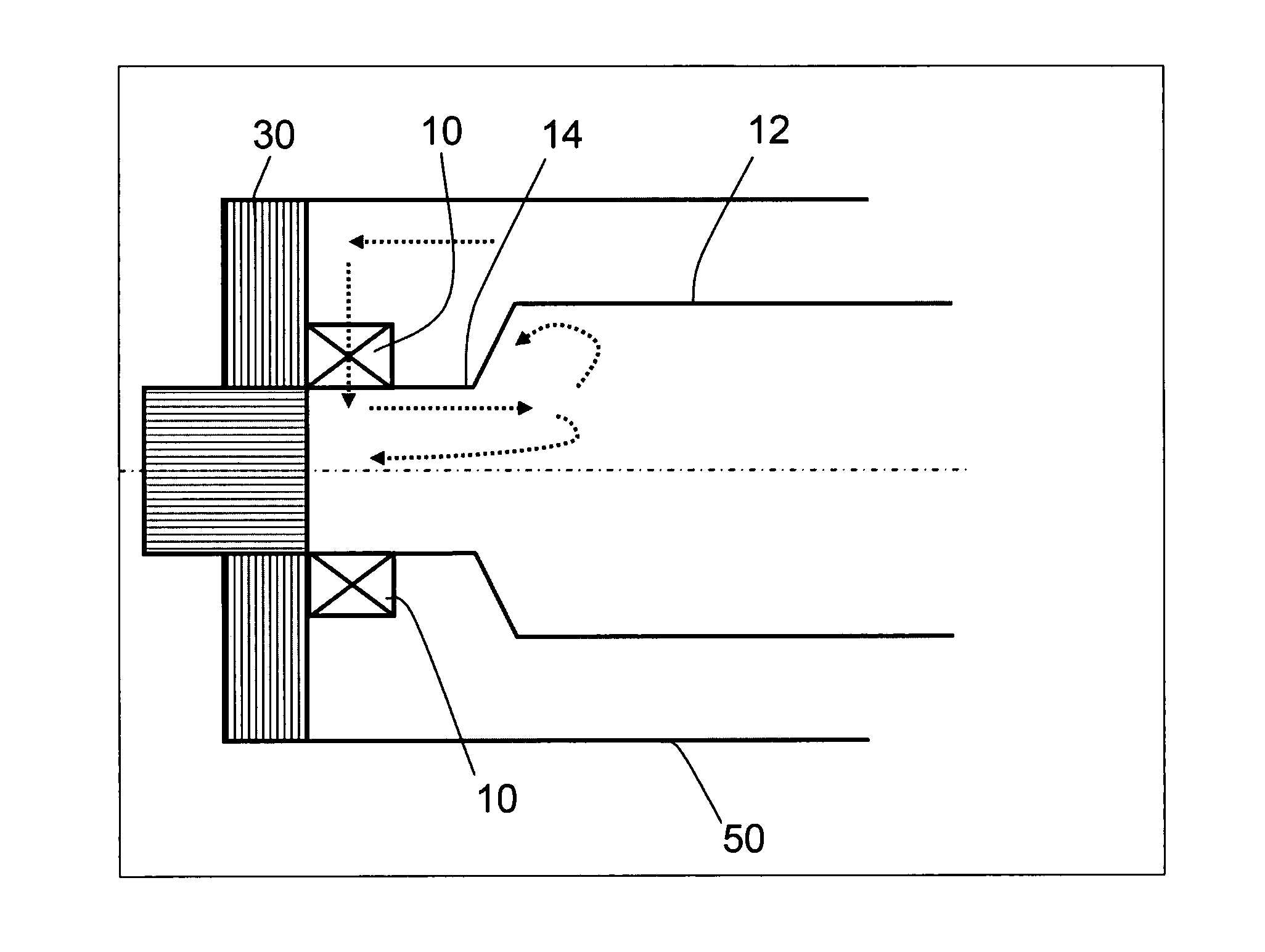
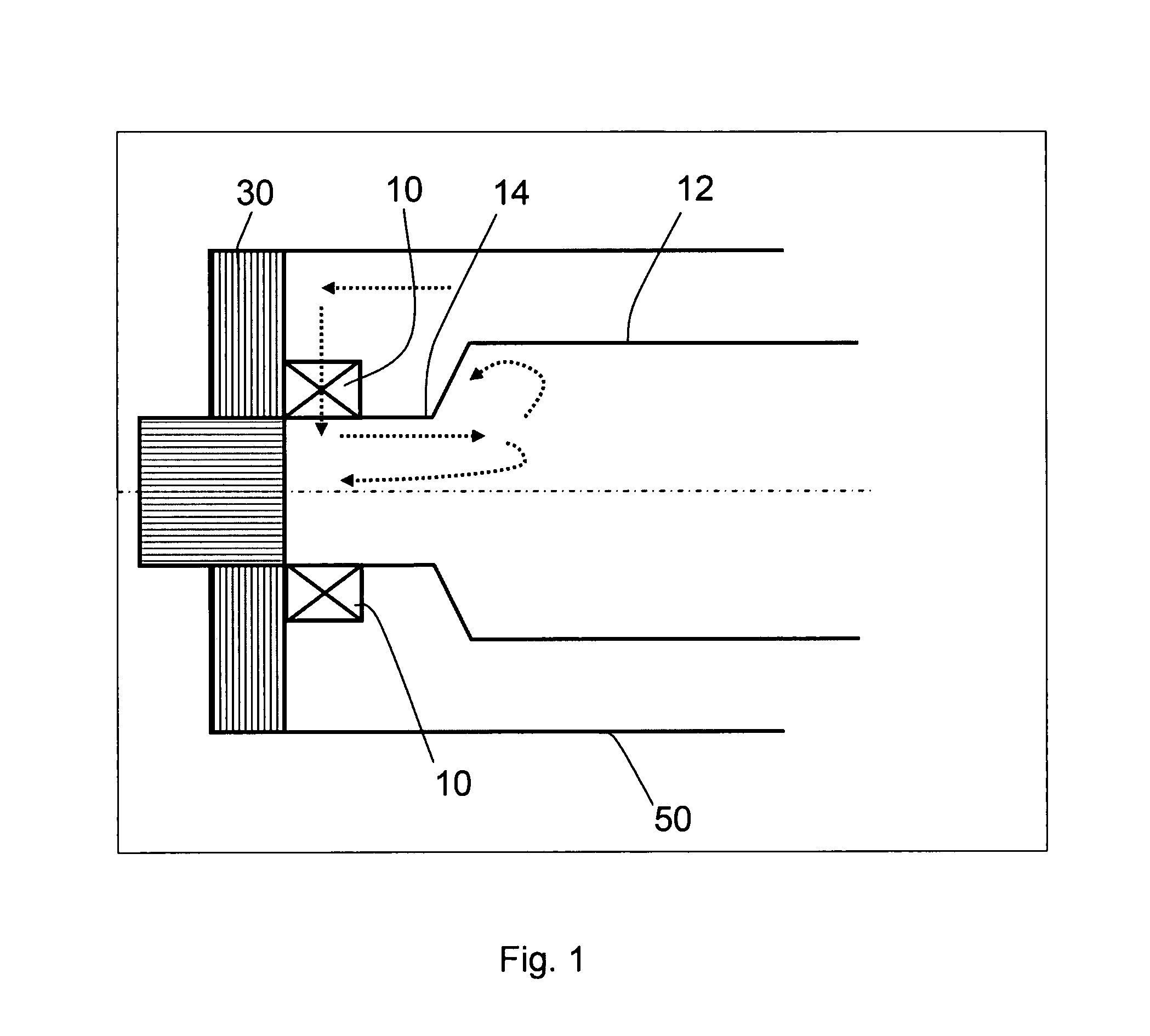
[0039]FIG. 1 of the present invention shows a cross-section side view of a combustion apparatus, particularly of a gas turbine engine, according to the prior art. The combustion apparatus shown in FIG. 1 shows a combustion chamber 12, a pre-chamber 14 located upstream of the combustion chamber 12, a first device 10 for mixing a fuel with an oxidant, wherein the first device 10 is located upstream of the pre-chamber 14. Moreover, the combustion apparatus according to the prior art also comprises a back plate 30 and an outer casing 50.

[0040]An oxidant, such as for example air, is supplied by a compressor to the first device 10. The flow direction of the oxidant is indicated by dotted arrows shown in the upper part of FIG. 1. The first device 10 is adapted for mixing a fuel, which can be supplied by fuel galleries through the back plate 30, with the oxidant supplied by a not shown compressor. The first device 10 outputs the oxidant or the fuel / oxidant mix into the pre-chamber. In the c...


PUM


Abstract

A combustion apparatus includes a first device for mixing a fuel with an oxidant, a combustion chamber in which combustion of the fuel / oxidant mix takes place, a pre-chamber located between the first device and the combustion chamber and a second device for outputting a gas flow into the pre-chamber. The first device is adapted for outputting the oxidant or the fuel or the fuel / oxidant mix to the pre-chamber. The second device is located upstream of the first device and wherein the second device is arranged for mixing fuel with a gas and the gas flow is a fuel / gas mix.

Description

CROSS REFERENCE TO RELATED APPLICATIONS[0001]This application is the US National Stage of International Application No. PCT / EP2011 / 058911, filed May 31, 2011 and claims the benefit thereof. The International Application claims the benefits of European application No. 10167460.4 EP filed Jun. 28, 2010. All of the applications are incorporated by reference herein in their entirety.FIELD OF INVENTION[0002]The present invention relates to a combustion apparatus. More particularly, the present invention relates to a radial burner with an axial pilot. Furthermore, the present invention relates to a gas turbine engine.BACKGROUND OF INVENTION[0003]In combustion systems combustion instabilities are a significant issue since these instabilities can result from hydrodynamic or thermoacoustic instabilities. Combustion systems, which use a high level of swirl to produce a flow structure with a central recirculation, produce a shear layer, in which a flame can stabilize. This swirling and the hig...

Claims


Application Information

Patent Timeline
15 Aug 2013
Publication
US20130205748A1
IPC
F02C3/00
CPC
F23D2900/00015; F02C3/00; F23R3/343; F23R3/286
Inventors
SANDERSON, VICTORIA