Wall-Mounted Corkscrew

a corkscrew and wall-mounted technology, applied in the field of corkscrews, can solve the problems of high constructive manufacturing cost and heavy corkscrews

Inactive Publication Date: 2007-12-20
B OLANETA Y JUARISTI SA
View PDF4 Cites 8 Cited by
  • Summary
  • Abstract
  • Description
  • Claims
  • Application Information

AI Technical Summary

Benefits of technology

[0006] A corkscrew of the mentioned type is proposed according to the present invention but which is structured such that it effectively resolves the drawbacks of the conventional embodiments of this type of corkscrew, providing very advantageous functional features.

Problems solved by technology

This embodiment is expensive to manufacture since the tubular body and the cover must be made separately, the fitting of a threaded coupling between necessary being later adapted.
In conventional corkscrews of this type, the drive part of the mechanism is metallic and is made by machining, which involves a high constructive manufacturing cost, further making the corkscrew very heavy.
This type of corkscrew is normally wall-mounted in a vertical position on a wall and the actuation lever thereof is usually left in a raised position so that it does not get in the way when it is not being used, and therefore there is a risk that said lever will lower by itself, possibly causing accidents; therefore in the construction of such corkscrews it is necessary to include some provisional retention means for the lever in the mentioned upper position.
The position of the lever in the raised situation furthermore usually involves a drawback for the gripping thereof when actuating the corkscrew due to the little space between said lever and the mounting wall of the corkscrew.

Method used


Image

  • Wall-Mounted Corkscrew
  • Wall-Mounted Corkscrew
  • Wall-Mounted Corkscrew

Examples


Embodiment Construction

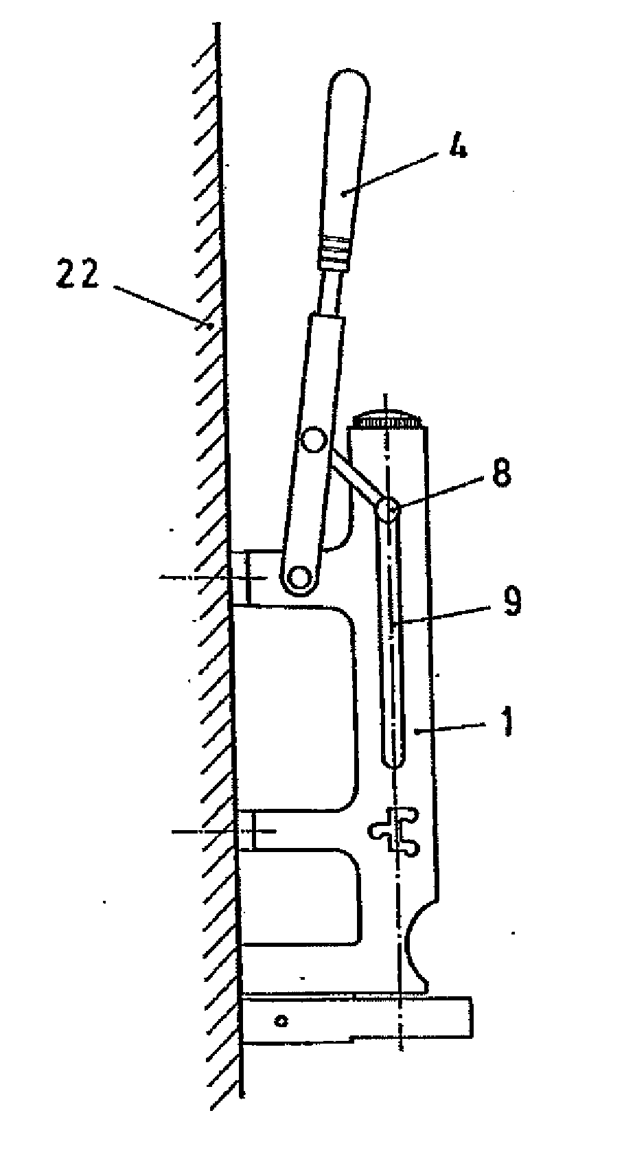
[0021] The object of the invention relates to a corkscrew of the type fixed to a wall or a similar area for their use, proposing a constructive embodiment improving the functional and structural features of said corkscrews.

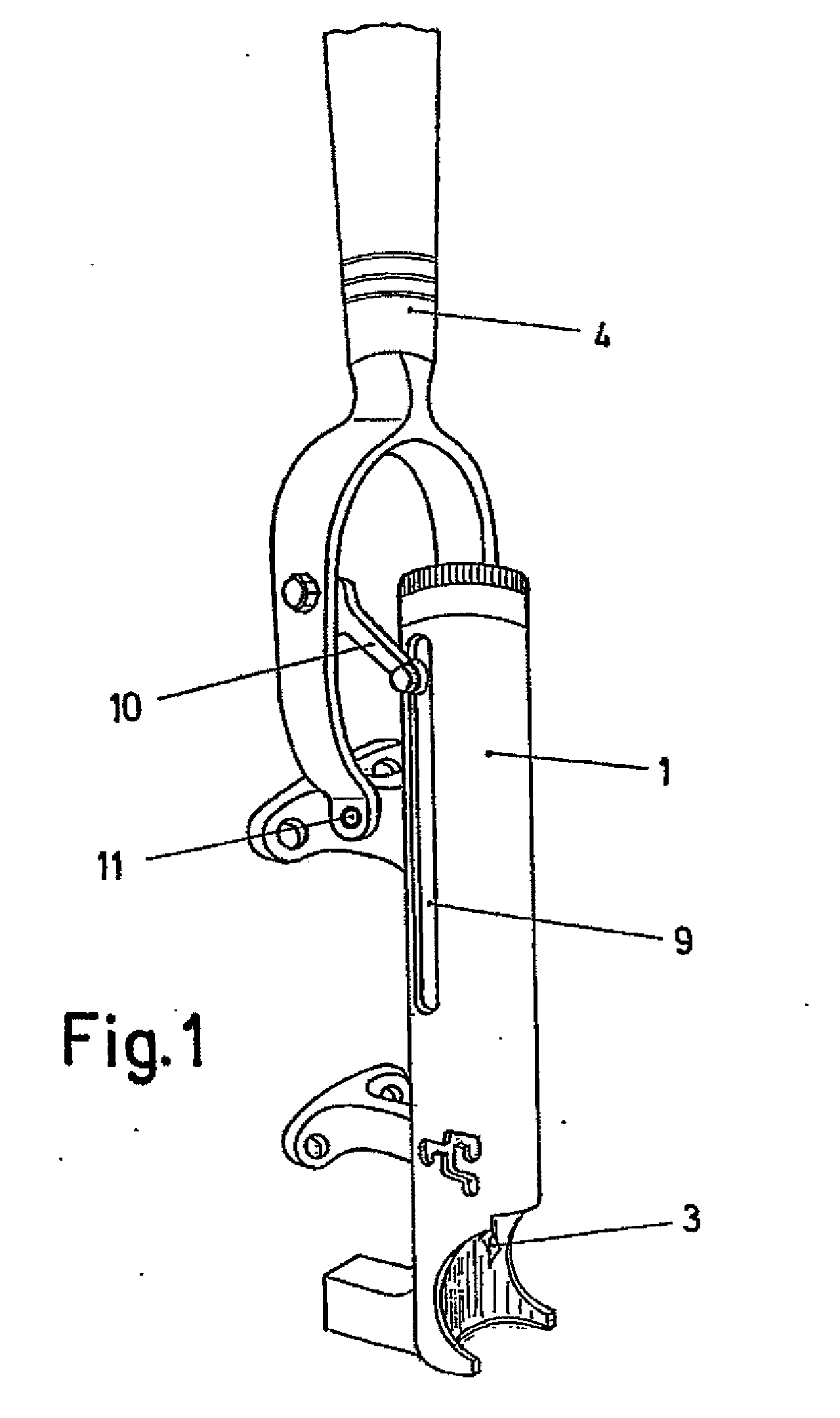
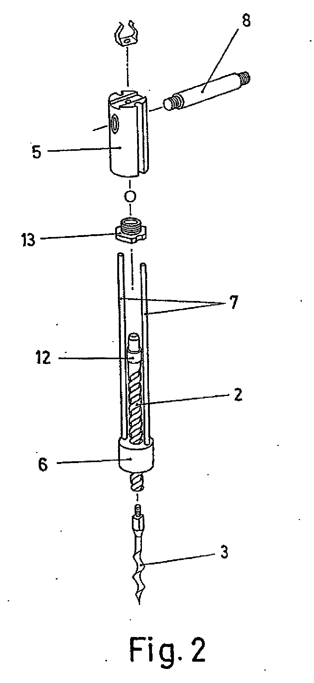
[0022] A corkscrew of this type consists of a tubular body (1) inside of which a mechanism is housed comprising a screw (2) in relation to which the helical shaft (3) is coupled and intended for being inserted in corks to be extracted, being able to actuate the movement mechanism by means of an actuation lever (4).

[0023] The screw (2) of the mechanism is coupled to a drive part (5) in relation to which it is axially retained with freedom of rotation, further passing through a nut (6) which is provided in a guided assembly by means of rods (7) in relation to the drive part (5), provided with an axial freedom of movement between both parts but without the ability of rotation between them.

[0024] The drive part (5) is furthermore traversed by a transverse shaft (8)...


PUM


Abstract

The invention relates to a wall-mounted corkscrew comprising a mechanism which includes the helical shaft to be inserted into the cork and which is connected to an actuating lever. The aforementioned mechanism is housed inside a one-piece tubular body which is closed at one end and said mechanism comprises a plastic cylindrical part (15) in which a helical-shaft-bearing screw (2) is positioned with an axial freedom of movement. In addition, a backstop is disposed between a striction (7) inside the part (15) and a transverse shaft (8) which passes therethrough.

Description

FIELD OF THE INVENTION [0001] The present invention relates to corkscrews arranged in a mounting area and having a lever by means of which a mechanism including the helical shaft for removing the cork is actuated, providing an embodiment of said corkscrews with features that improve the operation and construction thereof. STATE OF THE ART [0002] Corkscrews in a fixed assembly include the helical shaft for removing the cork associated to a mechanism which is housed in a tubular body and which is actuated by means of an actuation lever, the tubular body being provided with an upper cover which can be removed for the assembly of the inner mechanism. This embodiment is expensive to manufacture since the tubular body and the cover must be made separately, the fitting of a threaded coupling between necessary being later adapted. [0003] The shaft-bearing mechanism comprises a screw including the helical shaft, said screw passing through a rotating actuation nut, whereas at the rear end it ...

Claims


Application Information

Patent Timeline
Patent Type & Authority Applications(United States)
IPC IPC(8): B67B7/04
CPCB67B7/0452
Inventor OLANETA ARAMBARRI, SANTIAGO
Owner B OLANETA Y JUARISTI SA
Why Eureka
Try Eureka