Detector head position calibration and correction for SPECT imaging apparatus using virtual CT

a technology of spect imaging and calibration of detector head position, applied in the field of nuclear medical imaging, can solve problems such as high cost of procedure, head deflection and alignment, and potential image blurring and distortion

Active Publication Date: 2007-12-20
SIEMENS MEDICAL SOLUTIONS USA INC
View PDF2 Cites 13 Cited by
  • Summary
  • Abstract
  • Description
  • Claims
  • Application Information

AI Technical Summary

Benefits of technology

[0016]The point source P is then adjusted so as to lie within a crosshair projected on detector panels at image center locations. The crosshair position is denoted as the center of the image reconstruction coordinate system. The detector panels are initially placed around the phantom at 0 and 180 degree locations for calibration of the absolute coordinate system origin in the X-Z plane, and the energy profile of the point source P is acquired. 2D Gaussian surfaces are fitted to the peak of the point source P profile for each detector, from which x and y displacement parameters are determine

Problems solved by technology

Among the various factors that cause SPECT image distortion, detector head deflection and alignment issues are among the largest sources of error.
However, the versatility of the mechanical platform amplifies the challenges involved in accurate detector head position calibration because it introduces the capability for new detector positions and accordingly the conventional projection geometry assumptions used in image reconstruction are no longer applicable, leading to potential for image blurring and distortion.
While one way to reduce such problems is mechanical measureme

Method used


Image

  • Detector head position calibration and correction for SPECT imaging apparatus using virtual CT
  • Detector head position calibration and correction for SPECT imaging apparatus using virtual CT
  • Detector head position calibration and correction for SPECT imaging apparatus using virtual CT

Examples


Embodiment Construction

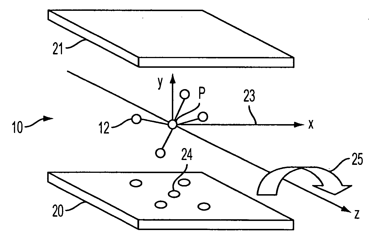
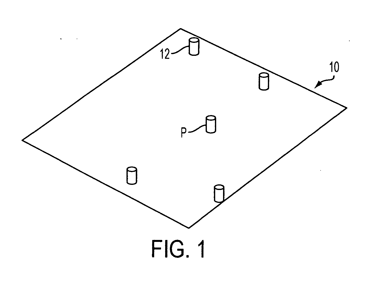
[0025]Referring to FIG. 1, a test phantom 10 is provided with a number of radioisotope point sources 12, with the center point source being denoted as point source P. In an exemplary embodiment, the test phantom comprises five point sources. Each point source comprises a capsule containing an appropriate amount of radioactive material, such as 99Tc or 57Co. The point source capsules 12 typically are mounted on a plate in a manner such that attenuation artifacts caused by interaction between the plate material and the point sources are minimized. As shown, the test phantom structure is such that a plurality of point source isotopes are located such that lines connecting any two pairs of said point source isotopes will be skewed with respect to each other.

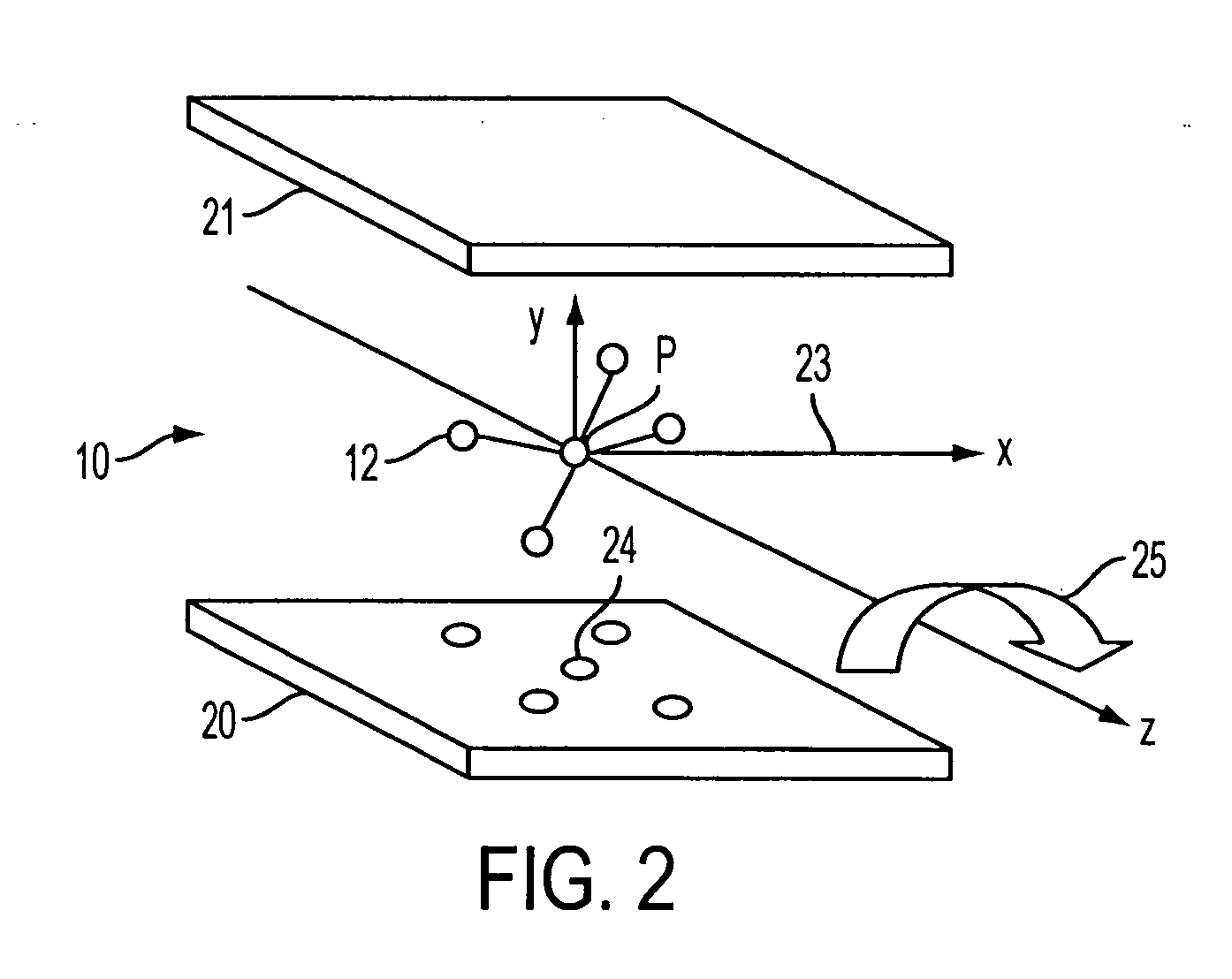
[0026]The phantom with loaded point sources is then subjected to SPECT imaging over four projection view angles (ie., 0, 90, 180 and 270 degrees). First, as shown in FIG. 2, panel detectors 20 and 21 are placed in 0 and 180 degree ro...


PUM


Abstract

A multiple point source test phantom is used for calibration of detector positioning of a nuclear medical imaging apparatus. An absolute coordinate system for the detectors is aligned to an image reconstruction space coordinate system by fitting a Gaussian surface to a peak of a center point source of said test phantom, and using displacement parameters as obtained from the fitted Gaussian surface to calculate a displacement correction parameter, which is used to move a patient bed of the imaging apparatus such that the image reconstruction space is aligned with the absolute coordinate system.

Description

BACKGROUND OF THE INVENTION[0001]1. Field of the Invention[0002]This invention relates generally to nuclear medical imaging, and more specifically, to improvement in calibration of multiple detector head positioning in SPECT imaging.[0003]2. Background and Prior Art[0004]In nuclear imaging, a patient is injected with or swallows a radioactive isotope which has an affinity for a particular organ, structure or tissue of the body.[0005]Gamma rays are then emitted from the body part of interest, are collimated by a collimator so that only gamma photons traveling in a direction perpendicular to the surface of a detector head are allowed to impinge on the detector head, and are detected by a gamma camera apparatus including the detector head, which forms an image of the organ based on the detected concentration and distribution of the radioactive isotope within the body part of interest. Nuclear images may be obtained using single photon emission (either planar or Single Photon Emission C...

Claims


Application Information

Patent Timeline
IPC IPC(8): G01D18/00G01T1/166G12B13/00
CPCG01T1/1648
Inventor WANG, SHARON XIAORONGFANG, JOSEPH
Owner SIEMENS MEDICAL SOLUTIONS USA INC
Why Eureka
Try Eureka