Crawler Frame Mounting Structure For Construction Machinery

a technology for construction machinery and clamping frames, which is applied in soil-shifting machines/dredgers, roofs, transportation and packaging, etc., can solve the problems of easy crack generation around side portions, easy damage to parts connected in this way, so as to improve durability and increase the axial force of the tie bolts

Active Publication Date: 2007-12-20
KOMATSU LTD
View PDF7 Cites 8 Cited by
  • Summary
  • Abstract
  • Description
  • Claims
  • Application Information

AI Technical Summary

Benefits of technology

[0022] According to the present invention, the plates attached to the tips of the leg portions not only close the end faces of the box constructions but also function as strength members. The plates also increase axial forces of the tie bolts at the tips of the leg portions which are affected the most by an external force. In this way, an effect that a stress at welded portions and base materials of the leg portions generated due to a twist of the crawler frames is relaxed and the durability is improved can be achieved.

Problems solved by technology

A portion connected in this way can be easily damaged due to an influence of an external force which may be applied by a movement of the device while it is working.
This causes a problem that, due to an influence from the plates 53 attached to the tips, a crack is easily generated around side portions.
However, the method may cause another problem.
Thus, without sufficient control on fastening strengths of bolts, even when there is insufficiency in a fastening force for some of a plurality of bolts, this may be overlooked, and damage of a tie bolt or a crack in a welded portion near a protruding portion of a leg portion may occur.

Method used


Image

  • Crawler Frame Mounting Structure For Construction Machinery
  • Crawler Frame Mounting Structure For Construction Machinery
  • Crawler Frame Mounting Structure For Construction Machinery

Examples


Embodiment Construction

[0043] Hereinafter, embodiments of the crawler frame mounting structure for a construction machine according to the present invention will be described with reference to the drawings.

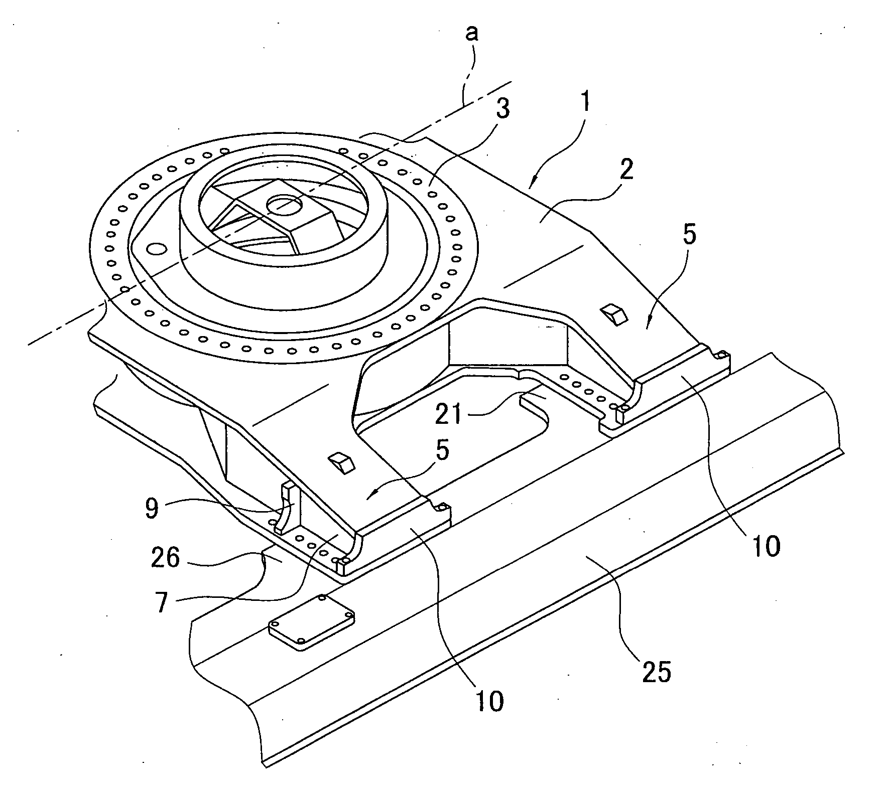
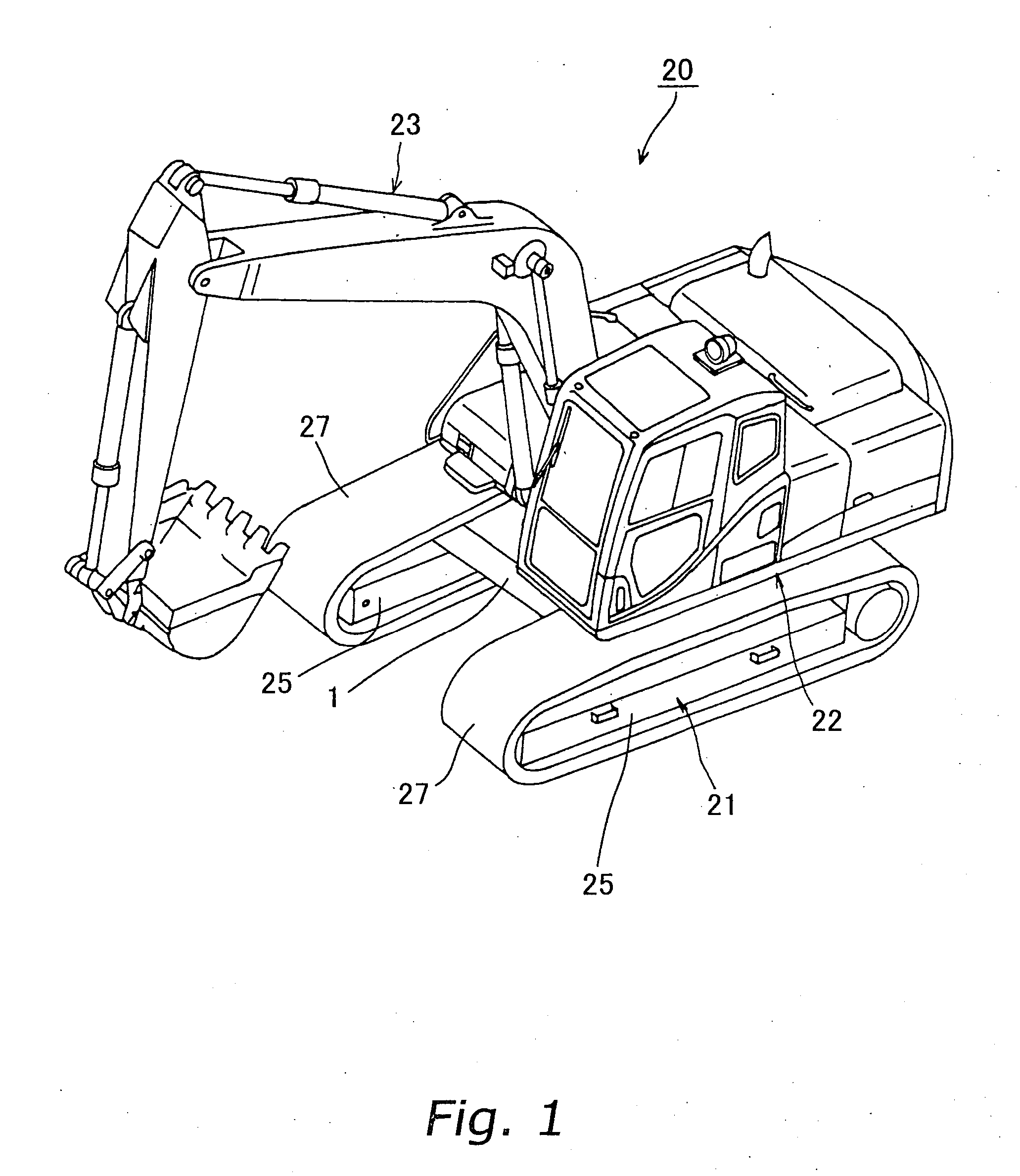
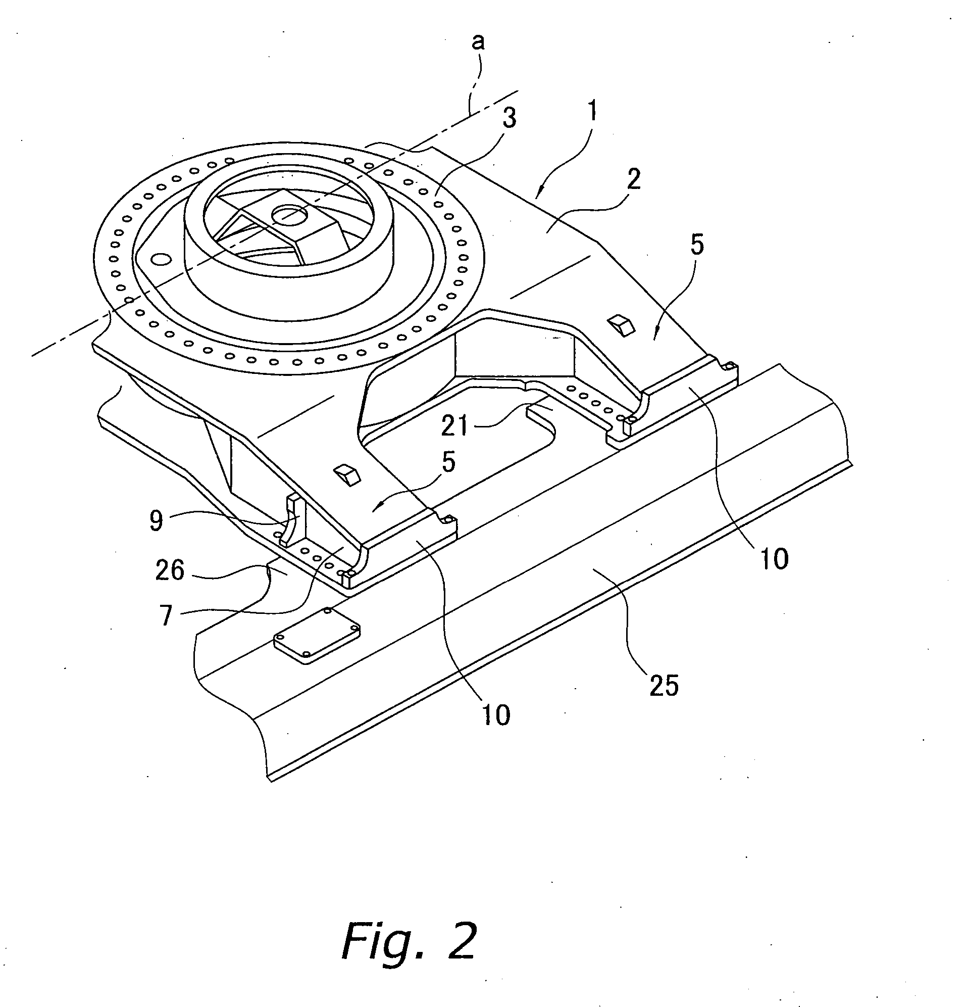
[0044]FIG. 1 is an entire perspective view of a hydraulic shovel to which the present invention is applied. FIG. 2 is a perspective view showing an outline of an important portion. FIG. 3 is an enlarged plan view of the important portion. FIG. 4A is a view of a leg portion of a center frame which is partially cut away and viewed from a tip side. FIG. 4B is a cross-sectional view cut along line A-A of FIG. 4A.

[0045] A base carrier 21 of a hydraulic shovel 20 is formed of a center frame 1 and a pair of crawler frames 25. The center frame 1 rotatably supports an upper rotating body 22 which is provided with an operating machine 23 and a power output section such as engine. Crawler tracks 27 which is driven and run are wound around and supported by the crawler frames 25.

[0046] The center frame 1 includes...


PUM


Abstract

A mounting structure for a center frame and crawler frames of a base carrier of a construction machine, which can increase durability without complicating the structure is provided. A crawler frame mounting structure for a construction machine includes a center frame configured to rotatably support an upper rotating body, fastening portions for fastening the center frame to crawler frames on right and left sides by front and rear leg portions, and end plates having widths wider than the width between attachment positions of a pair of vertical plates. The end plates including tie bolt holes formed on both right and left ends are welded.

Description

TECHNICAL FIELD [0001] The present invention relates to a crawler frame mounting structure for a construction machine of a type running by crawler tracks such as hydraulic shovels, crawler cranes, and the like. BACKGROUND ART [0002] Construction machine, typically, a hydraulic shovel includes a base carrier formed of a center frame which serves as a base, crawler frames, crawler tracks provided on the crawler frames, and a drive mechanism therefor. In general, the center frame and the crawler frames are assembled by bolting leg portions protruding from both sides of the center frame to an upper surface of the crawler frames. Such a structure allows the machinery to be dismantled for transportation. [0003]FIG. 6 shows a specific example of a joint portion between leg portions 51 of a center frame 50 and a crawler frame 55. In this exemplary connection, mounting seat portions 52 protrudes from both sides of the leg portions 51 having box constructions and mounting seats 56 are provide...

Claims


Application Information

Patent Timeline
Patent Type & Authority Applications(United States)
IPC IPC(8): B62D21/10
CPCE02F9/02B62D55/10B62D21/18B60Y2200/41
Inventor TAKEUCHI, MASAJIEKAWA, TADASHI
Owner KOMATSU LTD
Why Eureka
Try Eureka