
Solar power control using irradiance

a solar array and solar energy technology, applied in the direction of solar thermal energy generation, control systems, electrical equipment, etc., can solve the problems of difficult detection of power, difficult to meet the power requirements of load, and difficulty in detecting when sufficient available power is being generated by solar arrays

Inactive Publication Date: 2007-12-20
ENTECH SOLAR
View PDF8 Cites 37 Cited by
  • Summary
  • Abstract
  • Description
  • Claims
  • Application Information

AI Technical Summary

Benefits of technology

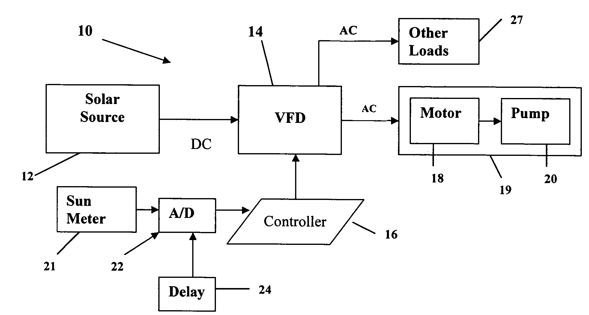
[0015]An aspect of the invention is an apparatus for converting DC power from a solar DC source to AC power to drive an AC motor, including a variable frequency drive (VFD) which produces an AC output from a DC input; a controller operatively associated with the VFD; a sun meter connected to the controller for applying a solar irradiance signal to the controller; wherein the controller controls the VFD to apply its AC output to the motor when the solar irradiance signal is at or above a threshold value. The controller may further control the frequency of the AC output of the VFD in response to changes in the solar irradiance signal.
[0016]Another aspect of the invention is a system including a solar DC source; a variable frequency drive (VFD) connected to the solar DC source to produce an AC output from a DC input; a controller operatively associated with the VFD; a sun meter connected to the controller for applying a solar irradiance signal to the controller; an AC motor connected to the AC output from the VFD; wherein the controller controls the VFD to apply its AC output to the motor when the solar irradiance signal is at or above a threshold value. The controller may further control the frequency of the AC output of the VFD in response to changes in the solar irradiance signal.

Problems solved by technology

The detection of when sufficient available power for an application is being generated by a solar array is difficult.
One cannot depend on the solar voltage from the solar array since the initial voltage is power limited until sun conditions raise the energy level.
The detection of power can be difficult since it is the product of two variables, voltage and current.
However, because of changes in both the source and the load, it can be difficult to meet the power requirements of the load.
Thus it can be difficult to efficiently operate an AC pump from a solar array.
However, if the motor continues to run at the same speed, e.g. 60 Hz, then as the voltage drops, the current must increase to meet the power requirements, until the increased current can damage the motor.
Thus, controlling motors at fixed frequency is very difficult.
However, it is difficult to track power.

Method used


Image

  • Solar power control using irradiance
  • Solar power control using irradiance
  • Solar power control using irradiance

Examples


Embodiment Construction

[0034]In accordance with the invention, solar irradiance is measured and is used to determine solar array power and to control delivery of the solar generated power to a load. The solar irradiance measurement is used to control the power system, e.g. motor drive, to match available solar power to the load, e.g. motor. In the simplest embodiment of the invention, the solar irradiance measurement is used to determine whether to turn a motor on or off. In more complex embodiments, the solar irradiance measurement is used to change motor speed.

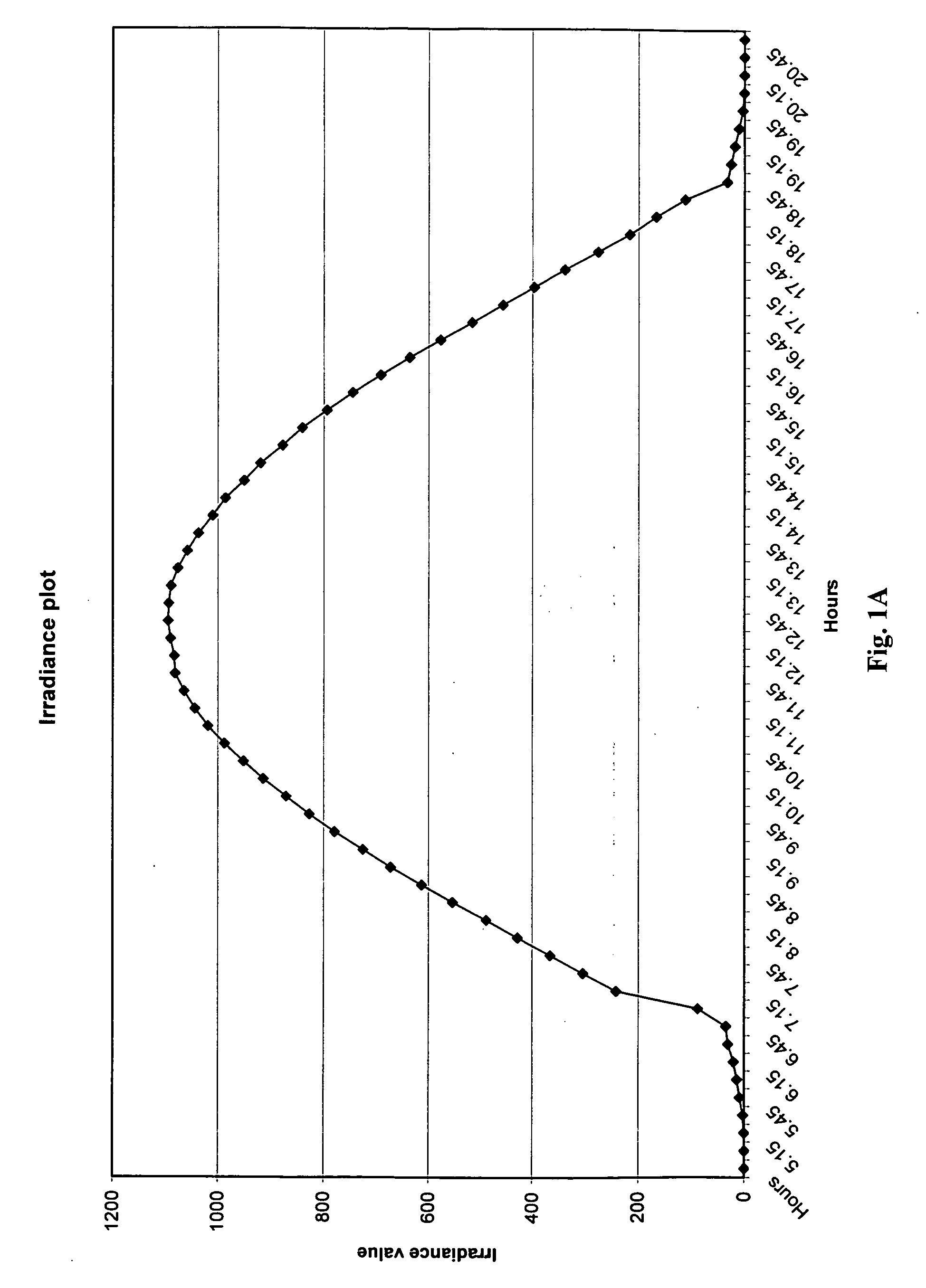
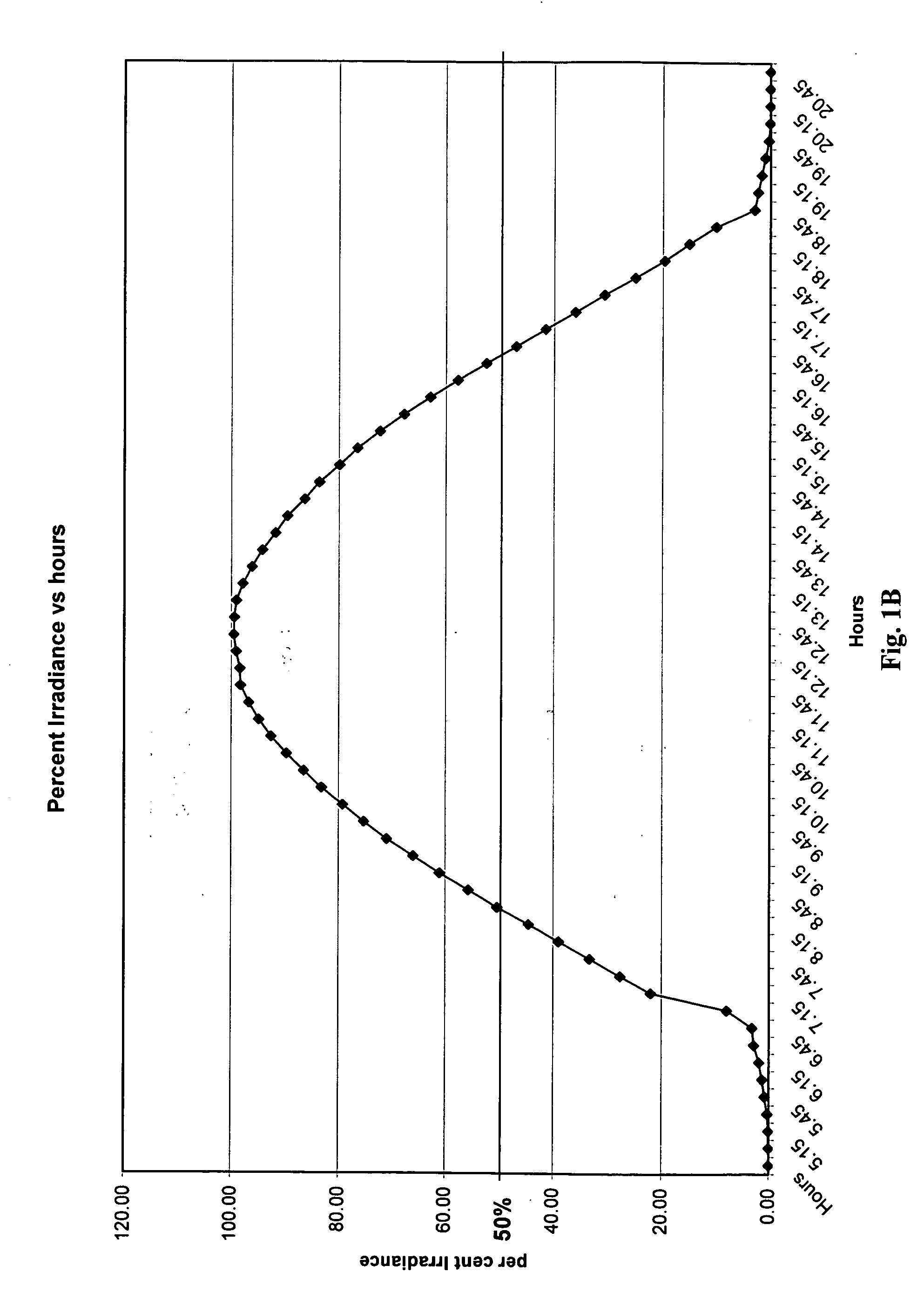
[0035]FIG. 1A is a plot of solar irradiance vs. time for daylight hours. The plot was made on a clear sunny day (idealized conditions). As shown, the plot starts gradually at daybreak, then increases rapidly until reaching a maximum of about 1095 W / m2 at about 12:30 pm, and then decreases until nightfall. Of course, the length of daylight hours will vary with location and time of year. FIG. 1B is a normalized irradiance plot that shows percentage ...


PUM


Abstract

Distribution of solar power in a solar DC sourcevariable frequency drive (VFD)—AC motor system is controlled by using solar irradiance. In addition, motor speed may be controlled as a function of available power, i.e. maximum power point tracking of motor speed, using solar irradiance.

Description

BACKGROUND OF THE INVENTION[0001]1. Field of the Invention[0002]The present invention relates generally to the operation of AC motors and other loads with AC motor drives that convert power from a solar DC source to AC, and more particularly to the detection of the power available from the solar DC source and control of the motor drive as the power from the solar DC source varies. A particular application is to solar powered water pumps.[0003]2. Description of Related Art[0004]The use of solar power is steadily increasing each year. As the demand for fossil fuels, particularly oil, increases, and the supply becomes tighter and the cost greatly increases, alternate energy sources become more attractive. More solar systems are being installed, not only to supplement or replace grid power, e.g. in residential applications, but to operate motors and non-motor loads, e.g. in commercial applications. Solar power systems can partly pay for themselves by net metering unused power back to th...

Claims


Application Information

Patent Timeline
Patent Type & Authority Applications(United States)
IPC IPC(8): H02P27/04
CPCY02E10/46F03G6/00
Inventor MCNULTY, THOMAS CHARLESHORTA, JUAN CARLOS
Owner ENTECH SOLAR
Learn More