Intelligent Interactive Lock and Locking System

a technology of intelligent lock and interactive lock, applied in the field of intelligent lock and locking system, can solve the problems of prone to power failure, physical damage to mechanical parts, damage to electronic parts too, and easy disruption of electrical conta

Inactive Publication Date: 2007-12-20
SEGEV EREZ
View PDF4 Cites 76 Cited by
  • Summary
  • Abstract
  • Description
  • Claims
  • Application Information

AI Technical Summary

Benefits of technology

[0007] The present invention discloses an intelligent lock and locking system with novel features, which provide significant advantages non-existent in prior art locks and locking systems. In particular, the invention discloses a “two-part” mechanical lock in which the locking mechanism is actuated by two separate elements: a mechanical element (cylinder) and an EM element (also referred to as “trigger”). Th...

Problems solved by technology

Since the lock system in McLintock's application is purely electrical, it is prone to power failures.
A major disadvantage of such combined units is that physical damage to the mechanical part damages the electronic part too.
The key in such combined units supplies the power to the cylinder, and the electrical contact is prone to disruption.
Another major disadvantage of “single part” unitary locks, either electrical, mechanical, or combined electromechanical (EM), is that tampering may disable the lock functionality.

Method used


Image

  • Intelligent Interactive Lock and Locking System
  • Intelligent Interactive Lock and Locking System
  • Intelligent Interactive Lock and Locking System

Examples


Embodiment Construction

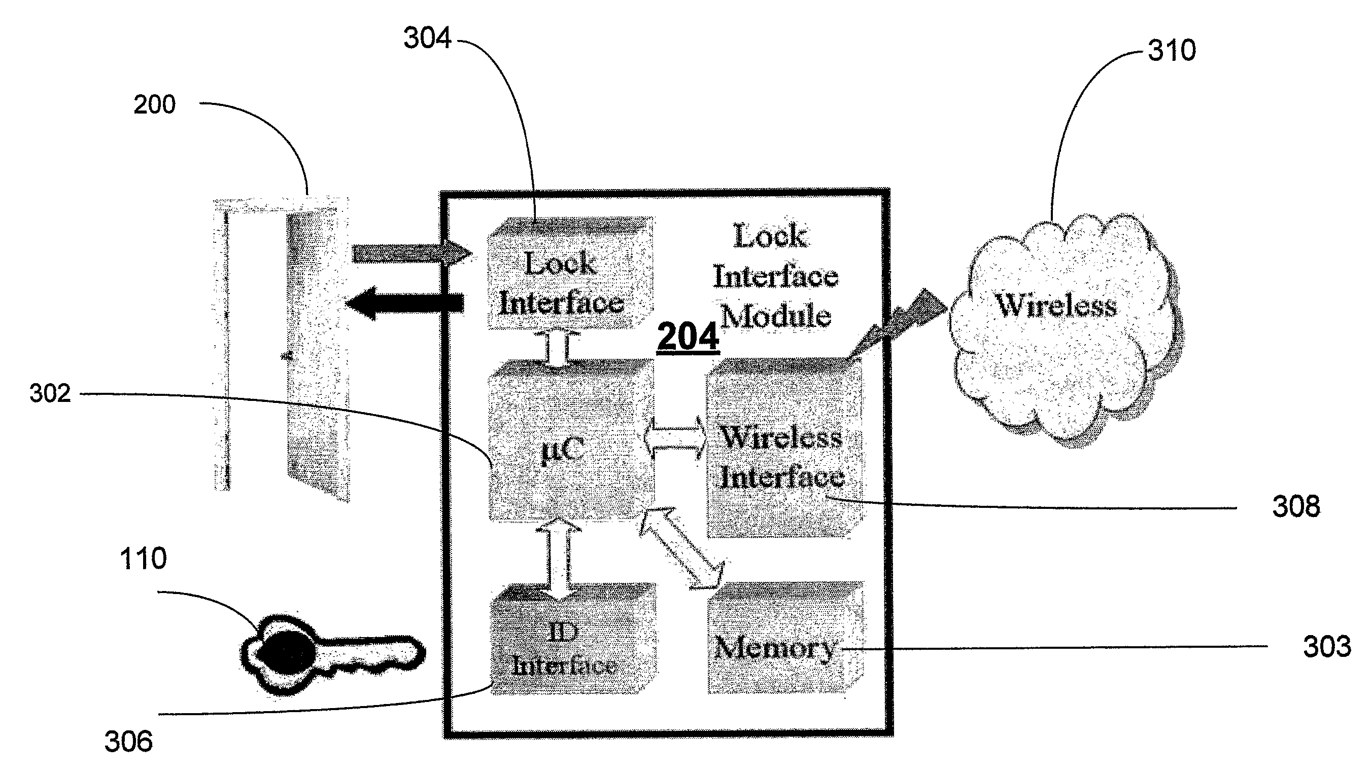
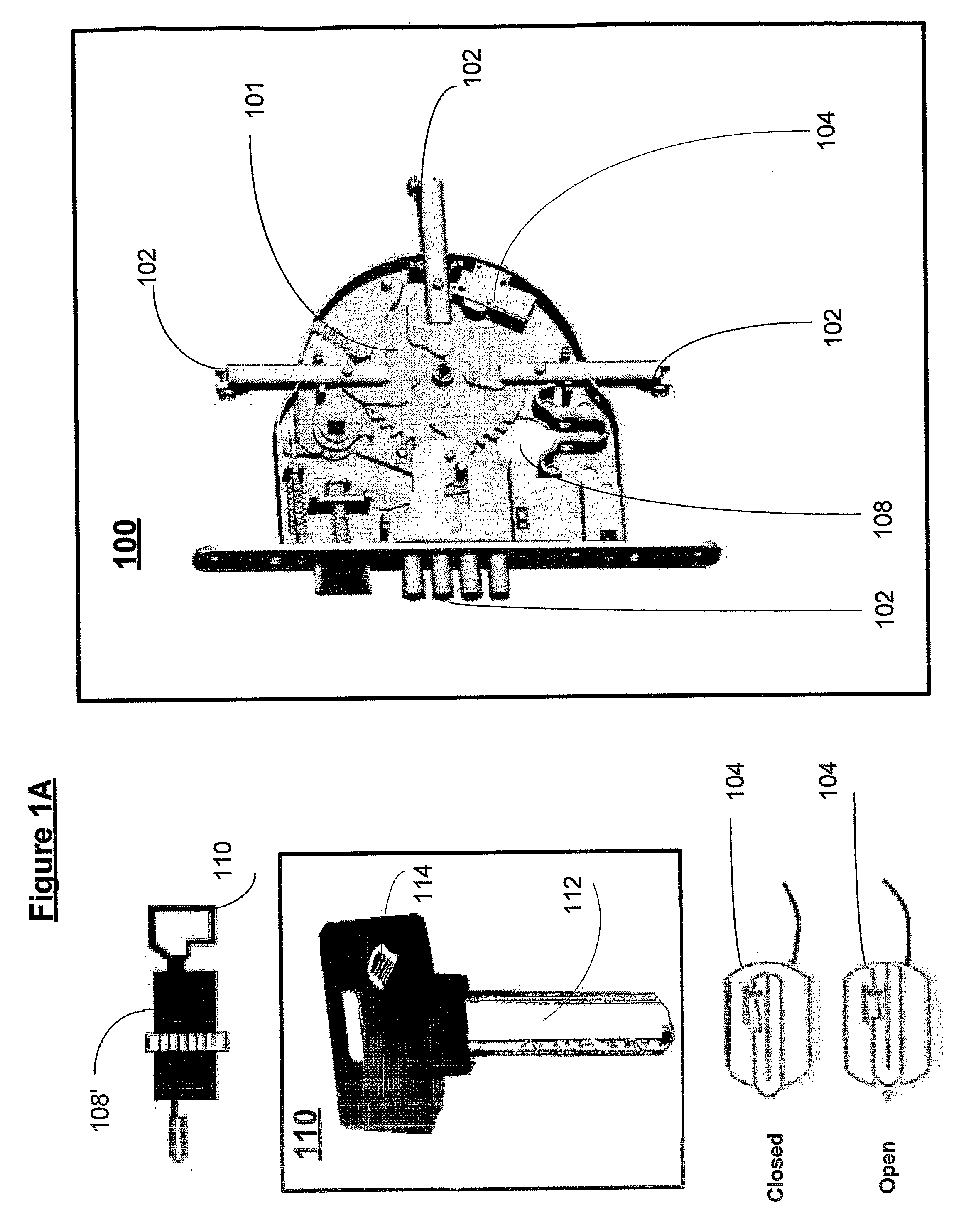
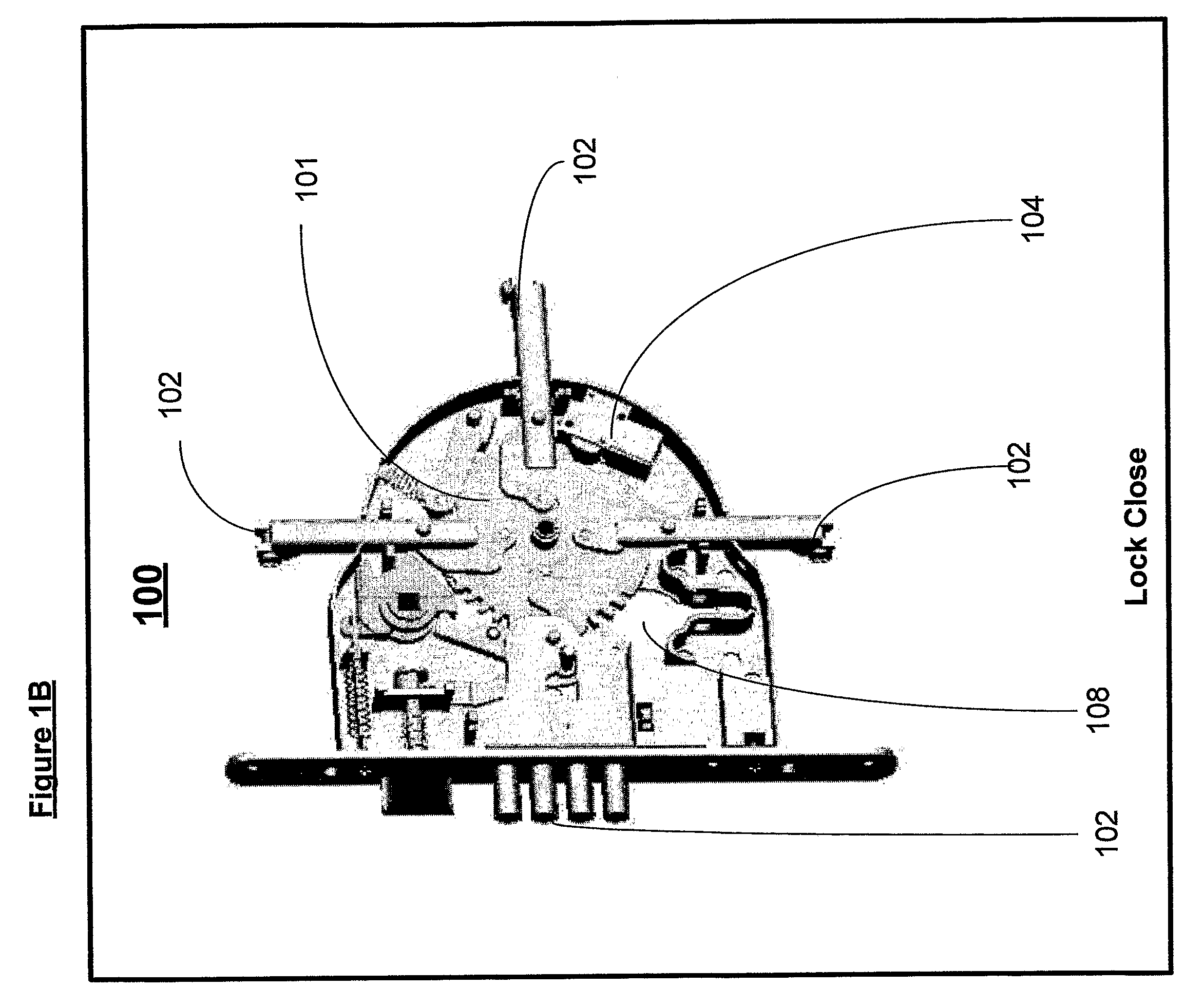
[0034]FIG. 1 shows schematically details of an exemplary intelligent two-part EM lock unit (or simply “intelligent lock”) 100, which in this example is based on a typical mechanical lock. In FIG. 1A, lock 100 comprises a locking mechanism 101 operative to move and position locking bars (or levers) 102 in at least two positions: open and closed. Lock 100 further comprises an electromagnetic element (“trigger”) 204 operative to engage mechanism 101. Trigger 104 may exemplarily be an electrically actuated element such as the “Active Latch” by Servocell Ltd, larlow, Essex CM20 2BN, UK. The trigger is shown schematically in FIG. 1A in more detail in two positions: in a locked position and in an open position. It will be apparent to one skilled in the art that the EM trigger may be actuated by other means (e.g. magnetically, piezo-electrically, etc.), directly through a physical link or remotely, e.g. by wireless means. Lock 100 further comprises a cylinder hole 108 into which a cylinder ...


PUM


Abstract

An intelligent lock comprises a mechanical element operative to provide two lock position upon a proper actuation, and an electromechanical (EM) trigger separate from and coupled to the mechanical element and operative to control the actuation. When included in an intelligent locking system, the lock is remotely controllable through a monitoring and control unit, operative to relay commands to the EM trigger.

Description

FIELD OF THE INVENTION [0001] The present invention relates in general to locking systems and more particularly to intelligent locking systems comprising at least one electromechanical component. BACKGROUND OF THE INVENTION [0002] Known traditional lock systems are based on stand-alone, hard to access mechanical units (usually made from steel), each having a matching key that enables locking or unlocking a lock unit. Any person who holds a matching key can open the lock. [0003] Stand-alone electronic lock systems are also known, and widely used in places like hotels, office buildings, security locations with restricted access, etc. Some systems of this type use an electronic card (usually a credit card type), which includes the information required to access a specific lock. The information is stored on the electronic card itself. The card is entered into or swiped through the lock, enabling or disabling (e.g. opening or closing) the lock. Other electronic lock systems may include b...

Claims


Application Information

Patent Timeline
IPC IPC(8): G05B19/00
CPCE05B17/042E05B47/0657E05B2047/0094E05C9/16G07C9/00896G07C2009/00769E05C9/06
Inventor SEGEV, EREZGAN, SHMUEL
Owner SEGEV EREZ
Why Eureka
Try Eureka