Antenna Control System

Active Publication Date: 2007-12-20
INTEL CORP
View PDF7 Cites 23 Cited by
  • Summary
  • Abstract
  • Description
  • Claims
  • Application Information

AI Technical Summary

Benefits of technology

[0019] This has the advantage that the operating element actuator can be mounted on an antenna, outside a protective cover of the antenna, without the need of any operating openings in the protective cover, or any physical engagement of the operating element actuator with the operating element.
[0020] The force field coupling may be a magnetic field coupling, and the magnetic field coupling may comprise a first magnet connected to the operating element and a second magnet connected to the operating element actuator. The magnets may constitute magnets from any of the group: permanent magnet or electromagnet such as a current coil. This has the advantage that the force field coupling may be established in an easy and cost efficient way.
[0021] The operating element actuator may consist of an electric motor with associated control electronics. This has the advantage that the tilt angle of a main beam of an antenna may be electronically controlled.
[0022] The electric motor and its associated control electronics may comprise a complete unit or complete module. This has the advantage that the module can be retrofitted to the antenna. As an alternative, said unit or module may be arranged to be mounted within the environmental protection (protective cover) of the antenna. This might be advantageous when the antenna is intended to only be used in connection with remote controlled electrical tilt.
[0023] The electric motor and its associated control electronics may be accommodated in a separate housing arranged to be secured to the antenna outside the environmental protection (protective cover) of the antenna. Said housing may be arranged such that it can be retrofitted to the antenna, preferably without opening the environmental protection of the antenna. This has the advantage that the module can be retrofitted to the antenna as a separate unit with an own protective cover separated from the protective cover of the antenna.
[0030] This has the advantage that the control electronics may be well suited for use in a communication system utilizing remote setting of the tilt of main beams of antennas in the communication system.

Problems solved by technology

One problem with both manual and remote downtilt, however, is to achieve an easy and reliable connection of the operating element actuator to the operating element.

Method used


Image

  • Antenna Control System
  • Antenna Control System
  • Antenna Control System

Examples


Embodiment Construction

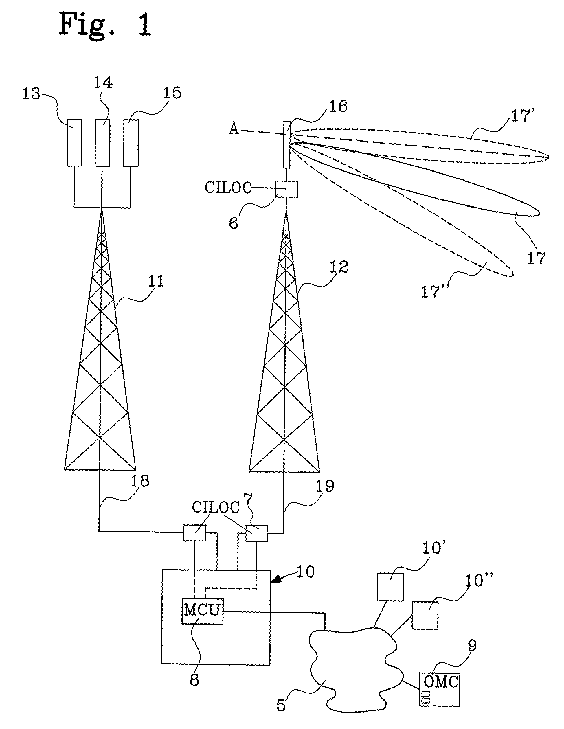
[0041] In FIG. 1 is shown part of a cellular communication system which beneficially may implement the present invention. The figure shows a base station 10 with two antenna frame structures, such as towers 11, 12. Three antennas 13, 14, 15 are mounted to the tower 11, while only one antenna 16 is mounted to the tower 12. Each antenna 13-16 transmits signals in a main lobe, of which only the main lobe 17 of antenna 16 is shown. In the figure, the main lobe 17 is directed slightly downwards. By use of phase shifting means, the main lobe 17 may, and, of course, in a similar manner main lobes of the antennas 13-15, independently of other main lobes be tilted up or down in a certain angle range relative to a horizontal plane A. This is indicated by upper and lower main beams 17′ and 17″. The angle range may e.g. be from 0° to 90°. Other angle ranges may, however, of course equally well be utilized.

[0042] The antennas are driven via feeder cables, such as coax cables 18 and 19 connectin...


PUM


Abstract

An antenna control system for setting the tilt angle of a main lobe of an antenna, in particular of an antenna constituting part of a base station in a mobile cellular communication system, said antenna comprising a plurality of antenna elements and phase shifting means for varying the phase of at least one signal being fed to said antenna elements, wherein adjustment of said phase of said signal is achieved by actuating an operating element, and wherein actuation of said operating element is achieved by operating an operating element actuator. The operating element actuator is coupled to the operating element of the phase shifting means by means of a force field coupling.

Description

FIELD OF THE INVENTION [0001] The present invention relates to antenna control system for setting the tilt angle of an antenna. More particularly, the system is of the kind defined in the preamble of claim 1. [0002] The present invention also relates to an operating element actuator as defined in the preamble of claim 21, an operating element of the kind defined in the preamble of claim 25, and an antenna as defined in the preamble of claim 29. BACKGROUND OF THE INVENTION AND RELATED PRIOR ART [0003] Today, mobile telephone systems usually are cellular systems, in which each cell in the system has at least one corresponding associated base station with at least one antenna for transmitting and receiving signals to / from e.g. user terminals of the system. [0004] The base station antennas are designed such that the inclinational angle of the beam radiated from such an antenna generally is deflected downwardly with an angle relative to a horizontal plane in order to define a specific ce...

Claims


Application Information

Patent Timeline
Patent Type & Authority Applications(United States)
IPC IPC(8): H01Q3/32H01QH01Q1/12H01Q1/24H01Q3/26
CPCH01Q1/246H01Q1/42H02K49/108H02K7/06H01Q3/32
Inventor FRANZON, BOOLSSON, TORBJORN
Owner INTEL CORP
Why Eureka
Try Eureka