
Remote video surveillance, observation, monitoring and confirming sensor system

a video surveillance and sensor system technology, applied in the field of video surveillance monitoring systems, can solve the problems of limited day and night capabilities of systems and limited success, and achieve the effect of increasing situational awareness

Inactive Publication Date: 2007-12-20
US REPRESENTED
View PDF3 Cites 29 Cited by
  • Summary
  • Abstract
  • Description
  • Claims
  • Application Information

AI Technical Summary

Benefits of technology

[0007]It is therefore an object of this invention to make a manportable video surveillance monitoring system. The system could be used, e.g., by the US military, to increase situational awareness providing force protection and security. Special reconnaissance or information gathering would also be a by-product of the system. Other spin-off users will be training facilities to capture and document their exercises.

Problems solved by technology

However, these systems' day and night capabilities are limited by ambient light or illumination.
Further, these systems have other challenges to making them manportable including a choice of external battery, solar panel or internal rechargeable military grade battery supply requirement, size, nighttime or obscured visibility either with too much or not enough ambient light, limited video RF links through or around urban structures and ease of operation and deployment.
For example, several manufactures have integrated cameras to there UGS for a visual confirmation with limited success due to a delay in video transmission.

Method used


Image

  • Remote video surveillance, observation, monitoring and confirming sensor system
  • Remote video surveillance, observation, monitoring and confirming sensor system
  • Remote video surveillance, observation, monitoring and confirming sensor system

Examples


Embodiment Construction

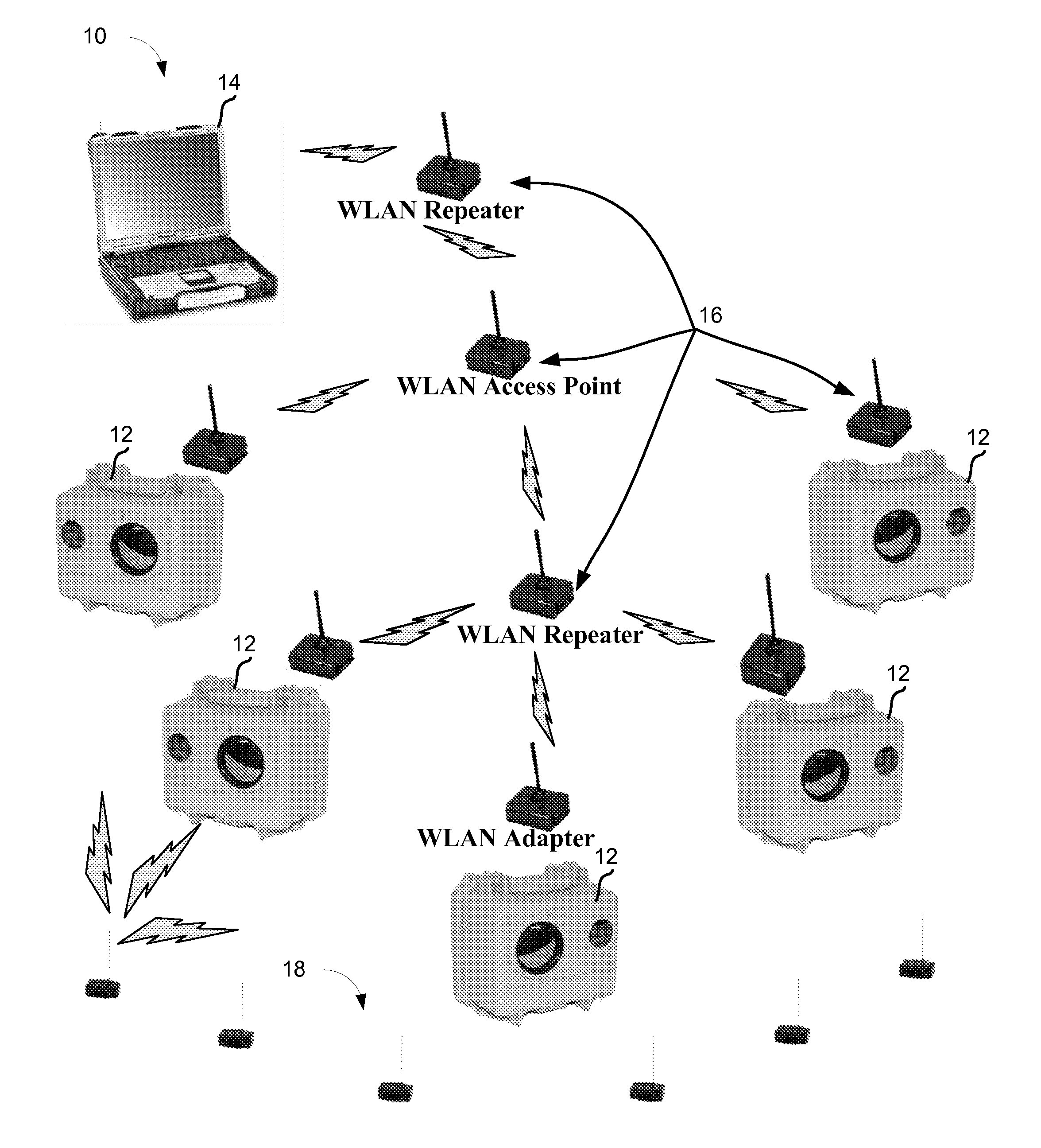
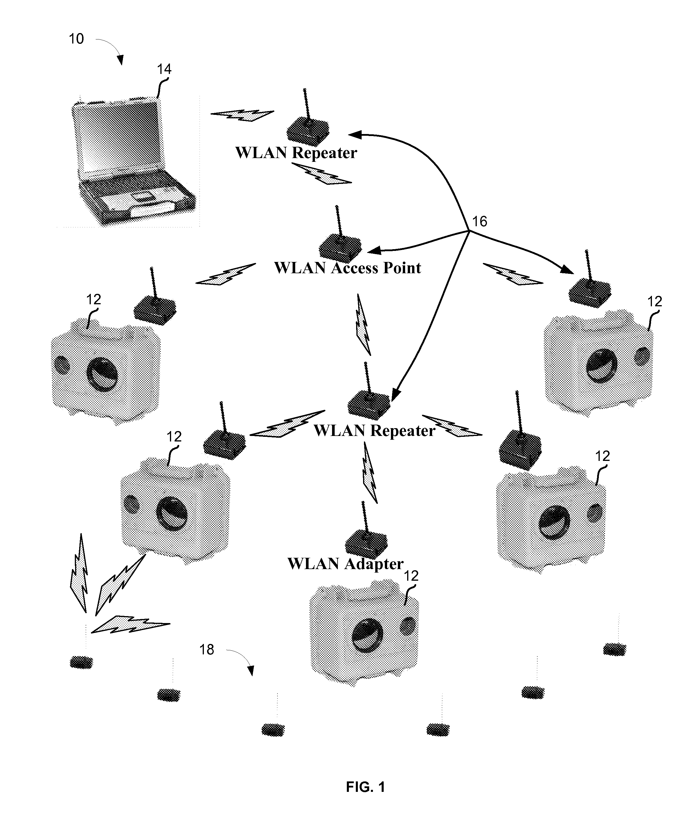
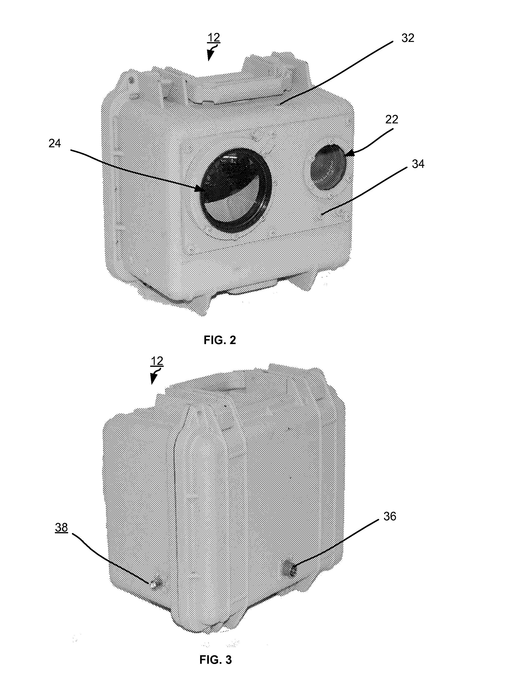
[0025]The present invention provides a manportable remote video surveillance, observation, monitoring and confirming sensor system 10. Referring now to the drawings, and initially to FIG. 1, the manportable remote video surveillance system 10 consists of five (5) different major components: 1) camera module(s) 12, 2) a base station 14, 3) wireless network module(s) 16, 4) a Mini Intrusion Detection System® (MIDS) 18 and 5) a field monitor 20 (FIG. 9). The system described below integrates emerging technologies in a wireless network, night vision cameras and Unattended Ground Sensors (UGS). To increase battery life, a timer relay is integrated to turn off the camera / transceiver between detection alerts.

[0026]Leveraging wireless network technology, video and audio can be transmitted over a secure local area network. Additionally, commercially available viewing software allows an operator to view / record transmissions (video and / or audio) from several cameras simultaneously on one compu...


PUM


Abstract

A video surveillance system includes at least one camera module electrically coupled to at least one Mini Intrusion Detection System® (MIDS). Additionally, a base station is electrically coupled to the at least one camera module to provide surveillance, monitoring, observation and confirmation of an item detected by the MIDS.

Description

GOVERNMENT INTEREST[0001]The invention described herein may be manufactured, used, sold, imported, and / or licensed by or for the Government of the United States of America.FIELD OF THE INVENTION[0002]The present invention generally relates to video surveillance monitoring systems, and, more particularly to remote video surveillance, observation, monitoring and confirming sensor systems.BACKGROUND OF THE INVENTION[0003]Most video surveillance monitoring systems are designed for use as home or business security systems. These systems are permanently installed by a professional in and around the home or business to be monitored. Some of these systems have day and night cameras. However, these systems' day and night capabilities are limited by ambient light or illumination. Further, these systems have other challenges to making them manportable including a choice of external battery, solar panel or internal rechargeable military grade battery supply requirement, size, nighttime or obscu...

Claims


Application Information

Patent Timeline
Patent Type & Authority Applications(United States)
IPC IPC(8): H04N7/18
CPCG08B13/19621G08B13/1966H04N7/185G08B15/001H04N7/181G08B13/19695
Inventor BACHELDER, PAUL W.MOYER, ANDREWCERUTTI, ANDREW C.BOWERS, RICKY E.
Owner US REPRESENTED
Learn More