Ophthalmologic imaging apparatus

a technology of ophthalmologic imaging and equipment, applied in the field of ophthalmologic imaging equipment, can solve the problems of inability to achieve chromatic aberration and inability to improve image quality in some cases

Inactive Publication Date: 2007-12-20
KK TOPCON
View PDF5 Cites 23 Cited by
  • Summary
  • Abstract
  • Description
  • Claims
  • Application Information

AI Technical Summary

Benefits of technology

[0020] According to the present invention, it can provide an ophthalmologic imaging apparatus for obtaining quality images within a short period of time with a plurality of light beams having different wavelengths. According to the present invention, it can provide an ophthalmologic imaging apparatus for synchronizing and controlling a wavefront measurement light source, a retina illumination light source, an imaging device for retinal images, and a wavefront compensation device according to the measured state of wavefront aberration. According to the present invention, it can compare oxygen saturation by the comparison of retinal images and display in detail the state of a retina in a diversified manner in color, enabled by combining images.

Problems solved by technology

To compare or combine images obtained with two or more light beams having different wavelengths in a conventional ophthalmologic imaging apparatus, however, it would be necessary to perform image compensation to conduct comparison because the imaging position and the focusing position lack reproducibility.
In addition, fundamentally, since the wavelength of light emitted from a light source used to measure wavefront aberration is different from that of light emitted from a light source used to observe a retina, there is a case that chromatic aberration cannot be removed by a compensation optical section and others, so that image quality deteriorates in some cases.

Method used


Image

  • Ophthalmologic imaging apparatus
  • Ophthalmologic imaging apparatus
  • Ophthalmologic imaging apparatus

Examples


Embodiment Construction

1. Outline

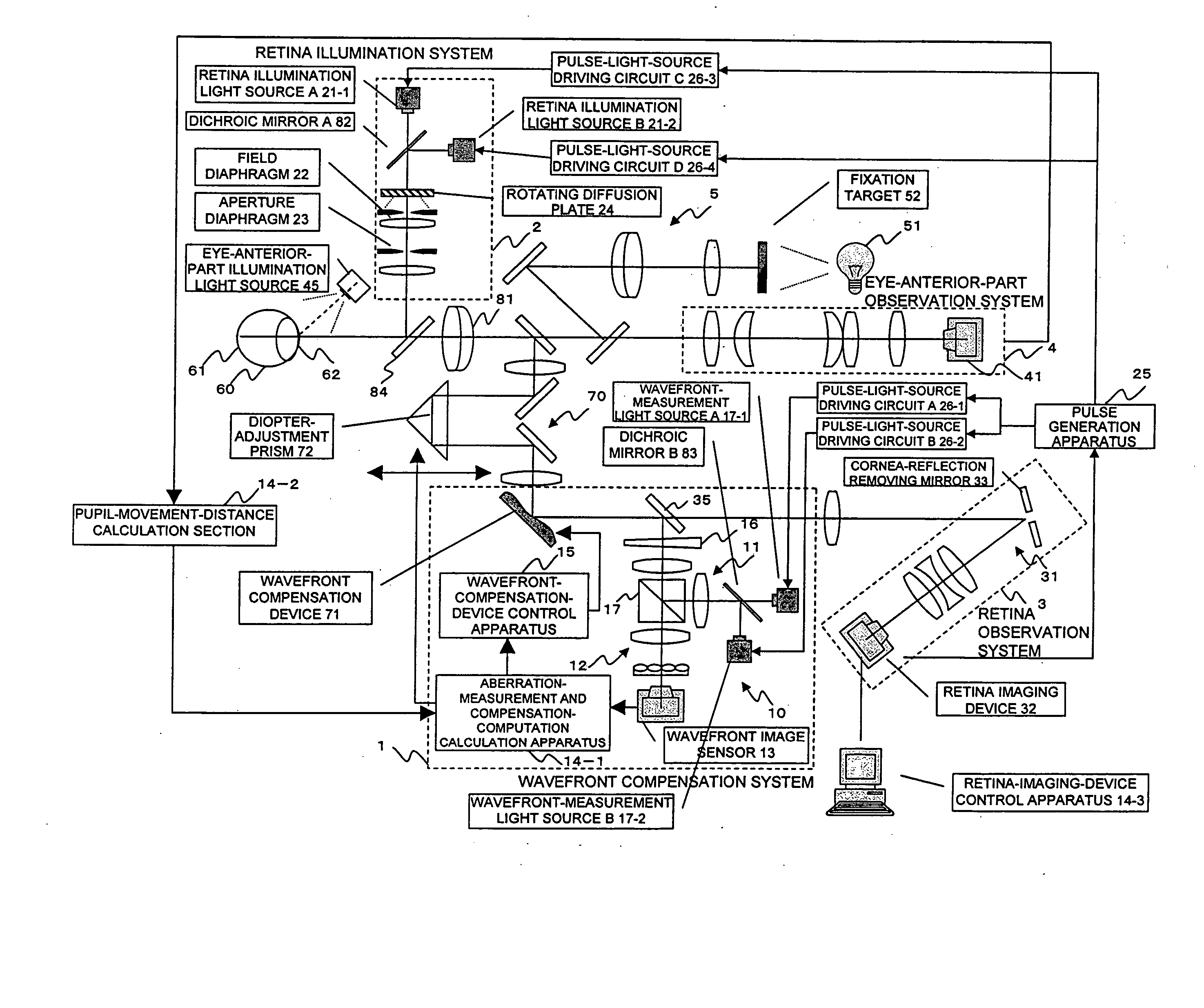
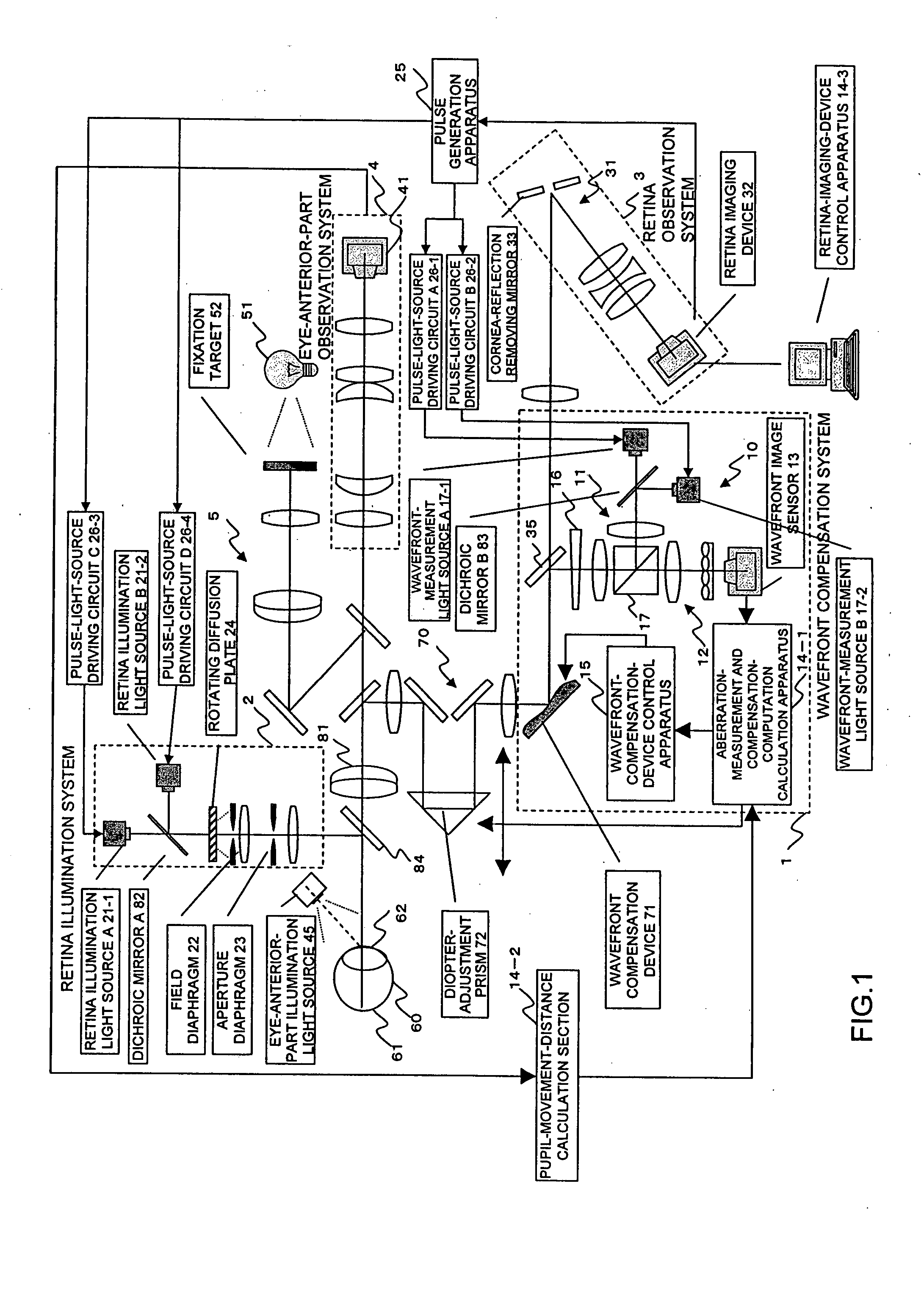
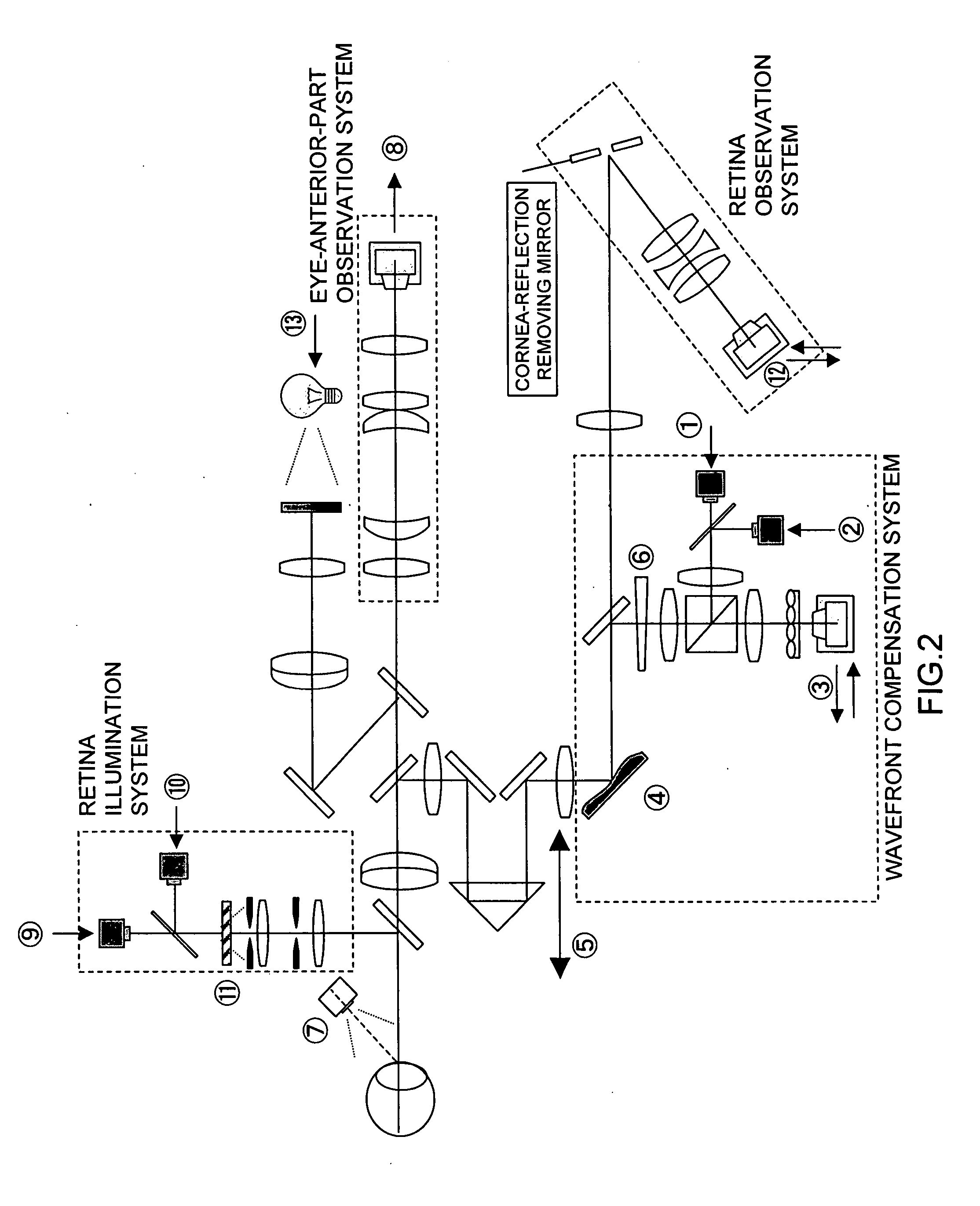
[0031] The present embodiment relates to an adaptive optics apparatus that allows spectrometric measurement for each selected wavelength. In the present embodiment, when light sources emit several pulse light beams having different wavelengths, for example, sequentially to an eye under measurement, spectroscopic retinal images can be obtained within a very short period of time. When a light source for wavefront measurement is used during a transfer period of an imaging device for retinal images, noise caused by the light source for wavefront measurement is prevented from affecting obtained retinal images. In addition, retinal images taken at a high magnification with two light beams having different wavelengths are compared to find many aspects such as the activity level of the retina and the distributions of L and M cone cells. If the light sources emit light beams having wavelengths corresponding to three primary colors, such as red, green, and blue, a color image can ...


PUM


Abstract

A first wavelength for measurement is selected from among a plurality of wavelengths. Aberrations at the first wavelength are measured with a wavefront-measurement light source having the first wavelength. A compensation optical section performs compensation so as to cancel out the measured aberrations. After the compensation, a retinal image is obtained from a retina imaging device using a retina illumination light source having the same wavelength as the wavefront-measurement light source. During image-data transfer from the retina imaging device, aberrations at a second wavelength are measured using another wavefront-measurement light source having the second wavelength. The compensation optical section performs compensation so as to cancel out the measured aberrations. After the compensation, a retinal image is obtained using another retina illumination light source having the same wavelength as the another wavefront-measurement light source. A difference image is obtained from the retinal images, and displayed or stored.

Description

BACKGROUND OF THE INVENTION [0001] 1. Field of the Invention [0002] The present invention relates to ophthalmologic imaging apparatuses, and more particularly, to an ophthalmologic imaging apparatus for obtaining retinal images at a high magnification within a short period of time with light beams having different wavelengths. [0003] 2. Description of the Related Art [0004] The following technologies have been disclosed by the assignee of present application. An eye-characteristic measurement apparatus which compensates for aberrations of an eye under measurement by a compensation optical section and measures precisely a minute aberration remaining after compensation is disclosed, for example, in Japanese Unexamined Patent Application Publication No. 2004-113405, No. 2004-159779, and No. 2004-159784. A retina observation apparatus which compensates a light beam reflected by an eye under measurement in order to improve retina-image quality and obtains an optimal image is disclosed, f...

Claims


Application Information

Patent Timeline
Patent Type & Authority Applications(United States)
IPC IPC(8): A61B3/10
CPCA61B3/14
Inventor YAMAGUCHI, TATSUOMIHASHI, TOSHIFUMI
Owner KK TOPCON
Why Eureka
Try Eureka