Optical signal transmitter and optical wireless communications network using it

a technology of optical wireless communication and optical signal transmitter, which is applied in the field of optical signal transmitter/receiver, can solve the problems of increasing installation cost, affecting the operation of the equipment, so as to reduce the installation cost, and reduce the output power

Inactive Publication Date: 2007-12-20
IND UNIV COOPERATION FOUND SOGANG UNIV OF +1
View PDF2 Cites 13 Cited by
  • Summary
  • Abstract
  • Description
  • Claims
  • Application Information

AI Technical Summary

Benefits of technology

[0017]The present invention provides an optical signal transmitter that requires a low output power for stable operation with mi

Problems solved by technology

However, this configuration suffers a disadvantage in that objects like traversing or moving within the communication path may destroy the.
Furthermore, the multiple signal paths increases the inter-symbol interferences (ISI) resulting the received signal resulting in degradation in the communication speed.
This hybrid communications also results in ISI together with degradation of the communication speed as in the NLOS communications.
First, as the positions of the ceiling and walls, and the inner space of the building varies with the height and area of the ceiling, it is hardly possible to provide standardized optical wireless communication services except for customized services according to a given building environment. Hence, the role of the field engineer is critical, which results in increase of the installing cost, and the difficulties of standardizing the optical wireless communication services increase the prod

Method used


Image

  • Optical signal transmitter and optical wireless communications network using it
  • Optical signal transmitter and optical wireless communications network using it
  • Optical signal transmitter and optical wireless communications network using it

Examples


first embodiment

[0042]Referring to FIG. 7, there is shown a base station according to the present invention. The base station BS 310 serves to perform the optical wireless communication within a given area or cell 350 by means of an optical signal transmitter 320 for irradiating the cell 350 with a data-modulated optical signal. The optical signal transmitter 320 includes an optical signal source 330 and an optical signal diffuser 340.

[0043]The optical signal source 330 for outputting data-modulated optical signals of a predetermined wavelength may be made of a laser diode (LD), light emitting diode (LED), optical fiber, etc. The optical fiber serves to transmit optical signals from one end to the other end. To this end, a separate optical source may be connected to one end of the optical fiber. The wavelength of the light used in the optical wireless communication is typically in the infrared region, i.e., equal to or above 650 nm, but may be in the visible light region.

[0044]An optical signal dif...

second embodiment

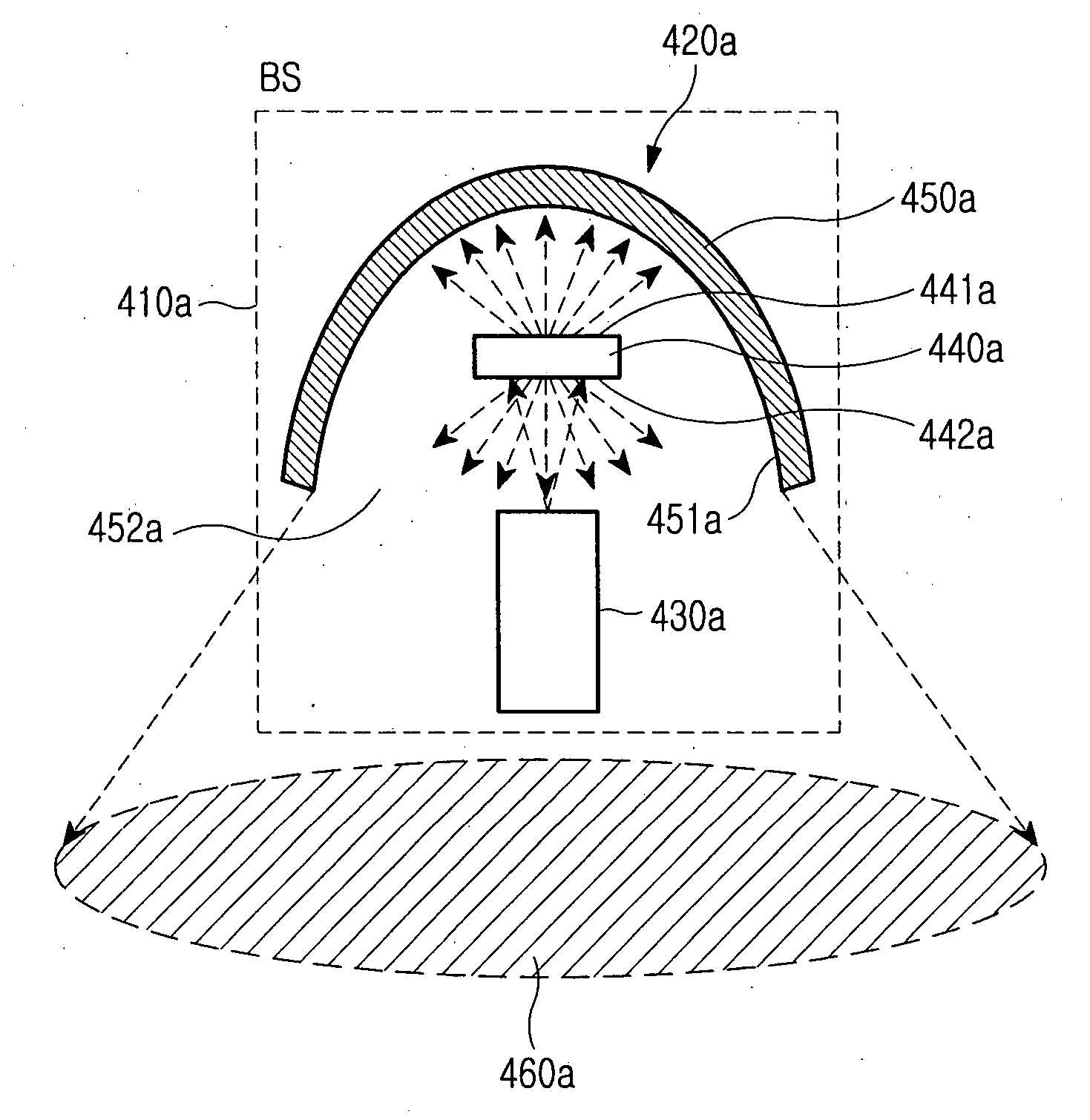
[0045]Referring to FIG. 8, there is shown the base station BS 410a performing the optical wireless communication within a cell 460a. The base station BS 410a includes an optical signal transmitter 420a for irradiating the cell 460a with a data-modulated optical signal. The optical signal transmitter 420a comprises an optical signal source 430a, an optical signal diffuser 440a, and a concave mirror 450a. The data-modulated optical signal has a predetermined wavelength.

[0046]The diffuser 440a, in this illustrative case, is a transmission / reflection-type with parallel upper and lower surfaces 441a and 442a. The diffuser 440a is arranged inside the concave mirror 450a with its upper surface 441a facing the inside 451a of the concave mirror 450a. The diffuser 440a is positioned between the concave mirror 450a and the light-generating output end of the optical signal source 430a so that the light-generating output end of source 430a faces lower surface 442a of diffuser 440a. The optical s...

third embodiment

[0048]FIG. 9 shows the base station BS 410b for performing the optical wireless communication within a cell 460b. The base station 410b includes an optical signal transmitter 420b for irradiating the cell 460b with a data-modulated optical signal. The optical signal transmitter 420b comprises an optical signal source 430b, an optical signal diffuser 440b, and a concave mirror 450b. The data-modulated optical signal has a predetermined wavelength.

[0049]The diffuser 440b is a transmission / reflection-type with parallel upper and lower surfaces 441b and 442b and is arranged inside the concave mirror 450b with the upper surface 441b facing the concave inside surface 451b of the concave mirror 450b. The optical signal source 430b is arranged between the upper surface 441b of the diffuser 440b and the inside of the concave mirror 450b so as to irradiate the upper surface 441b of the diffuser 440b with the optical signal, which diffuses, partly reflects and partly transmits the optical sign...


PUM


Abstract

An optical wireless communications network connects a plurality of communication cells, which are defined by dividing a local communication area, for enabling optical wireless communication in each of the communication cells. An optical signal transmitter is installed in each communication cell for irradiating the cell with a data-modulated optical signal to perform data transmission to a terminal located therein. The optical signal transmitter comprises an optical signal source for outputting the data-modulated optical signal, and an optical signal diffuser with a concave inside surface facing the output end of the optical signal source for diffusing and reflecting the data-modulated optical signal to irradiate the cell.

Description

CLAIM OF PRIORITY[0001]This application claims the benefit of the earlier filing date, pursuant to 35 U.S.C. §119, to that patent application entitled “Optical Signal Transmitter and Optical Wireless Communication Network Using It” filed in the Korean Intellectual Property Office on Jun. 20, 2006 and assigned Serial No. 2006-55542, the contents of which are incorporated herein by reference.BACKGROUND OF THE INVENTION[0002]1. Field of the Invention[0003]The present invention relates to an optical wireless communications, and more particularly to an optical transmitter / receiver that enables data communication by transmitting and receiving optical signals through free space.[0004]2. Description of the Related Art[0005]Generally there are three ways of constructing an optical wireless communications LAN (Local Area Network) for enabling optical wireless communication in a building as follows:[0006]First, LOS (Line-Of-Sight) communications requires a line-of-sight state between a base st...

Claims


Application Information

Patent Timeline
IPC IPC(8): H04B10/04H04B10/114H04B10/116
CPCH04B10/116H04B10/1149H04B10/11H04B10/50
Inventor KIM, BYUNG-JIKHWANG, SEONG-TAEKCHO, KYU-MANHUH, HYEONG-JUNKWON, KANG-HYUK
Owner IND UNIV COOPERATION FOUND SOGANG UNIV OF
Why Eureka
Try Eureka