Fireplace control system

Inactive Publication Date: 2007-12-20
HNI TECH INC
View PDF3 Cites 31 Cited by
  • Summary
  • Abstract
  • Description
  • Claims
  • Application Information

AI Technical Summary

Benefits of technology

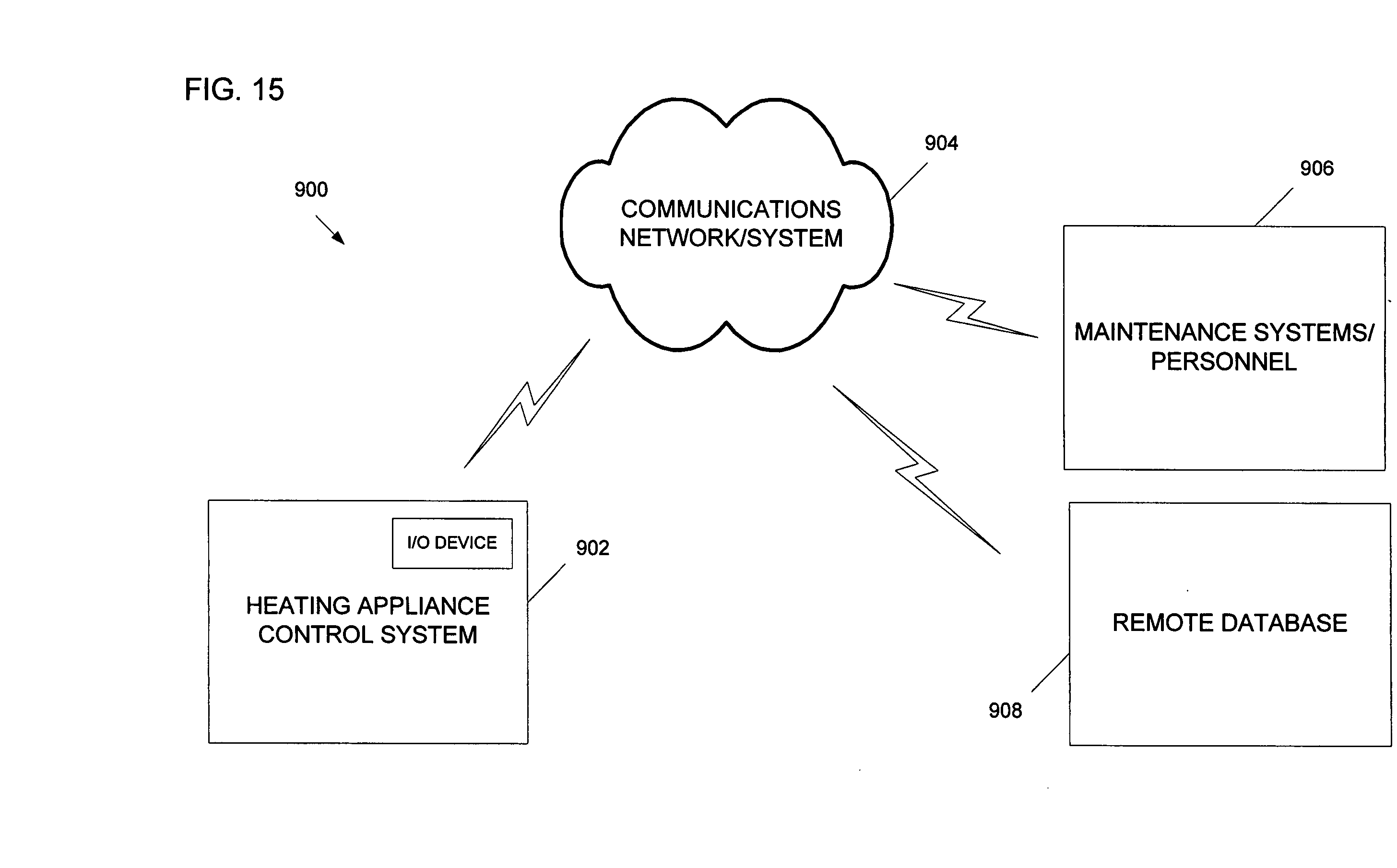
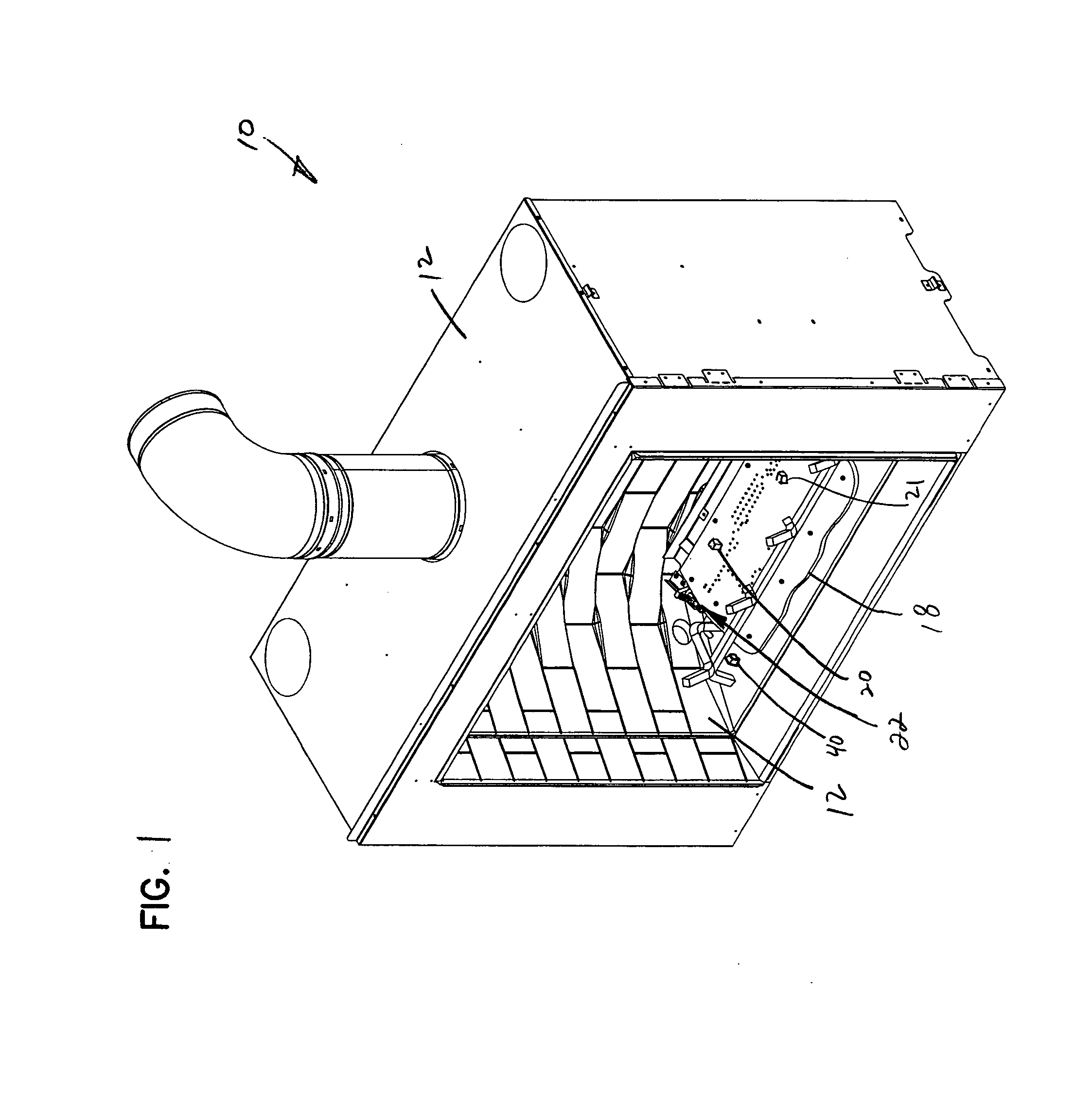
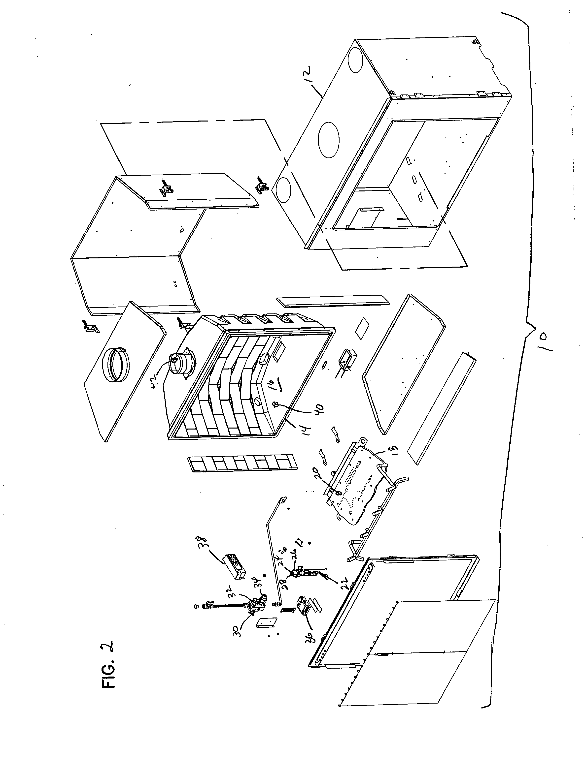
[0008] One aspect of the invention relates to a heating appliance control system that includes a pilot flame assembly, a main burner assembly, a gas valve, and a controller. The pilot flame assembly includes a pilot flame burner and at least one pilot flame sensor. The main burner assembly includes a main burner. The gas valve is coupled to the pilot flame and main flame burners. The controller is configured to control the variable gas valve in response to signals received from the pilot and main burner sensors. The controller is also configured to monitor a pilot flame at the pilot flame burner with the pilot flame sensor to confirm stabilization of the pilot flame or a pilot flame signal indicative of the pilot flame before activating the variable gas valve to supply gas to the main burner.
[0009] Another aspect of the invention relates to a method of generating a decorative flame in a heating appliance. The heating appliance includes a pilot flame assembly, a main burner assembly, a gas valve, and a controller. The method includes activating the gas valve to supply gas to the pilot flame assembly, igniting the pilot flame with an ignition source of the pilot flame assembly, monitoring the pilot flame to ensure stabilization of the pilot flame, and activating the gas valve to supply gas to the main burner assembly for generation of the decorative flame if the pilot flame is present.

Problems solved by technology

Providing a flame generated from gas can involve ignition, draft, safety and maintenance issues different from burning solid fuel.

Method used


Image

  • Fireplace control system
  • Fireplace control system
  • Fireplace control system

Examples


example battery

VI. Example Battery Backup Operation

[0092] Referring not to FIG. 13, a flow diagram illustrating the use of the back of battery pack in a heating appliance control system (e.g., battery backup 212 shown in FIG. 4) is shown and described. The method includes providing an AC power supply to the controller in a step 700 and concurrently positioning a battery backup pack with a control panel that is located outside the heating appliance in a step 702. If AC power is available in a step 704, the controller is operated using AC power in a step 706. If AC power is not available, there is a step of electrically connecting the battery pack to the controller through the control panel in step 708 and operating the controller using DC power from the battery pack in a step 710. In accordance with this method, it is possible to position the backup battery pack outside of the heating appliance. It is also possible according to this configuration to power a wall mounted control panel using the batt...


PUM


Abstract

A heating appliance control system that includes a pilot flame assembly, a main burner assembly, a gas valve, and a controller. The pilot flame assembly includes a pilot flame burner and at least one pilot flame sensor. The main burner assembly includes a main burner. The gas valve is coupled to the pilot flame and main flame burners. The controller is configured to control the variable gas valve in response to signals received from the pilot and main burner sensors. The controller is also configured to monitor a pilot flame at the pilot flame burner with the pilot flame sensor to confirm the presence of the pilot flame before activating the variable gas valve to supply gas to the main burner.

Description

BACKGROUND OF THE INVENTION [0001] 1. Field of the Invention [0002] The present invention generally relates to control systems for heating appliances, and more specifically relates to systems and methods for monitoring and controlling burners and ignition systems in a decorative heating appliance such as a fireplace, stove or fireplace insert. [0003] 2. Related Art [0004] Gas, electric, and wood burning heating appliances such as fireplaces, stoves and fireplace inserts are an efficient method for providing warmth and creating the appeal of a fire within a room. Fireplaces have become commonplace in today's building trades for both residential and commercial applications. Most new home construction designs include at least one, and often several fireplaces. Further, a significant number of remodeling projects are focused on fireplaces. [0005] Most known heating appliances include some type of heat control system that facilitates ON / OFF control, the level of heat output, and possibly...

Claims


Application Information

Patent Timeline
Patent Type & Authority Applications(United States)
IPC IPC(8): F23Q9/08
CPCF23N1/002F23N5/143F23N5/242F24C7/004F23N2029/02F23N2029/16F24B1/1808F23N2027/22F23N2229/02F23N2227/22F23N2229/16F24C3/006
Inventor MAIELLO, DENNIS R.BACHINSKI, THOMAS J.ACHMAN, GREGG A.
Owner HNI TECH INC
Why Eureka
Try Eureka