Endoscopic methods and devices for transnasal procedures

a technology of endoscopic methods and devices, applied in the field of medical equipment and methods, can solve problems such as the subtraction of deep structures using the available rigid instrumentation, and achieve the effects of reducing the amount of fluoroscopy and reducing radiation exposure to the user and the patien

Active Publication Date: 2007-12-20
ACCLARENT INC
View PDF111 Cites 335 Cited by
  • Summary
  • Abstract
  • Description
  • Claims
  • Application Information

AI Technical Summary

Benefits of technology

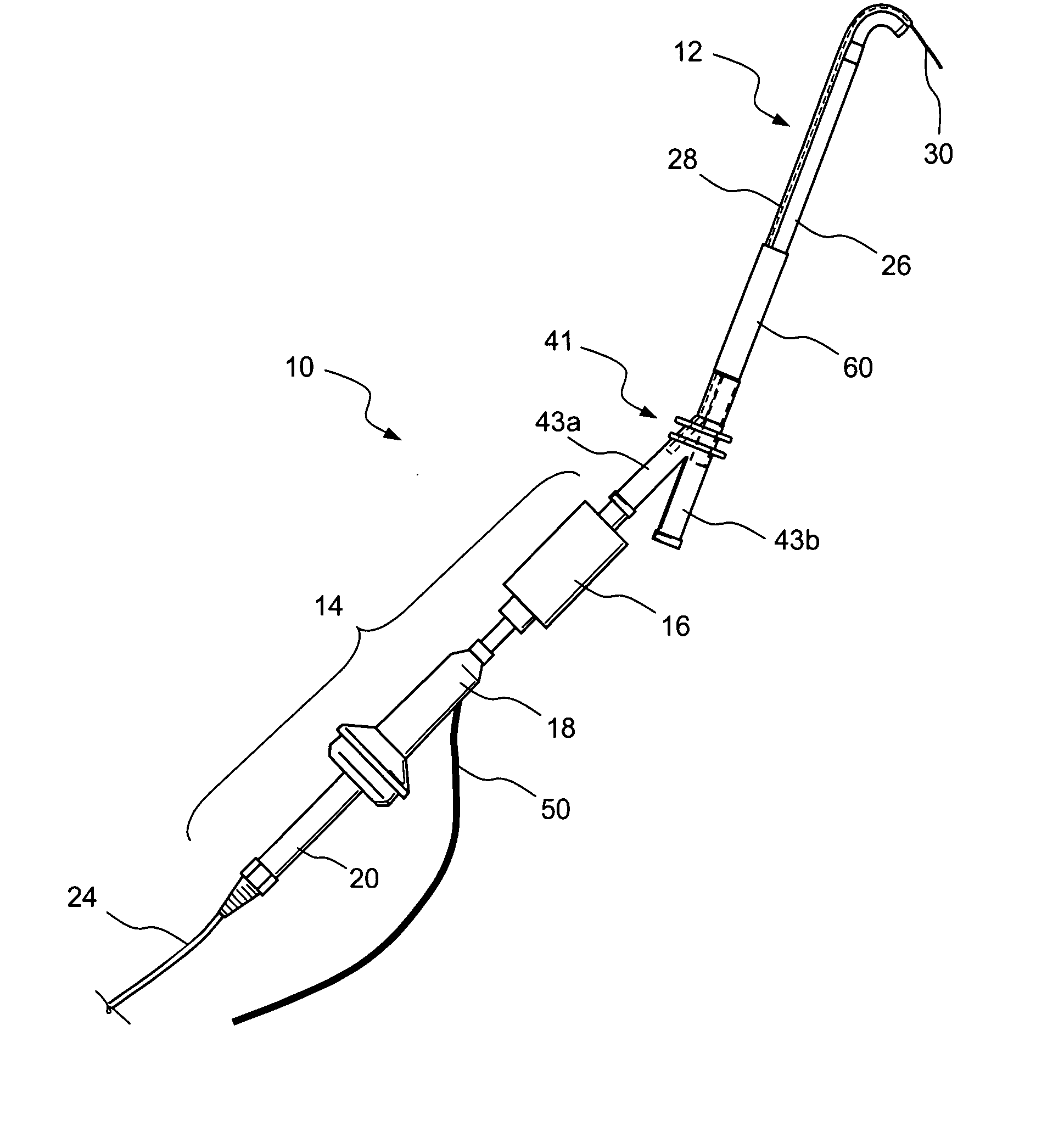
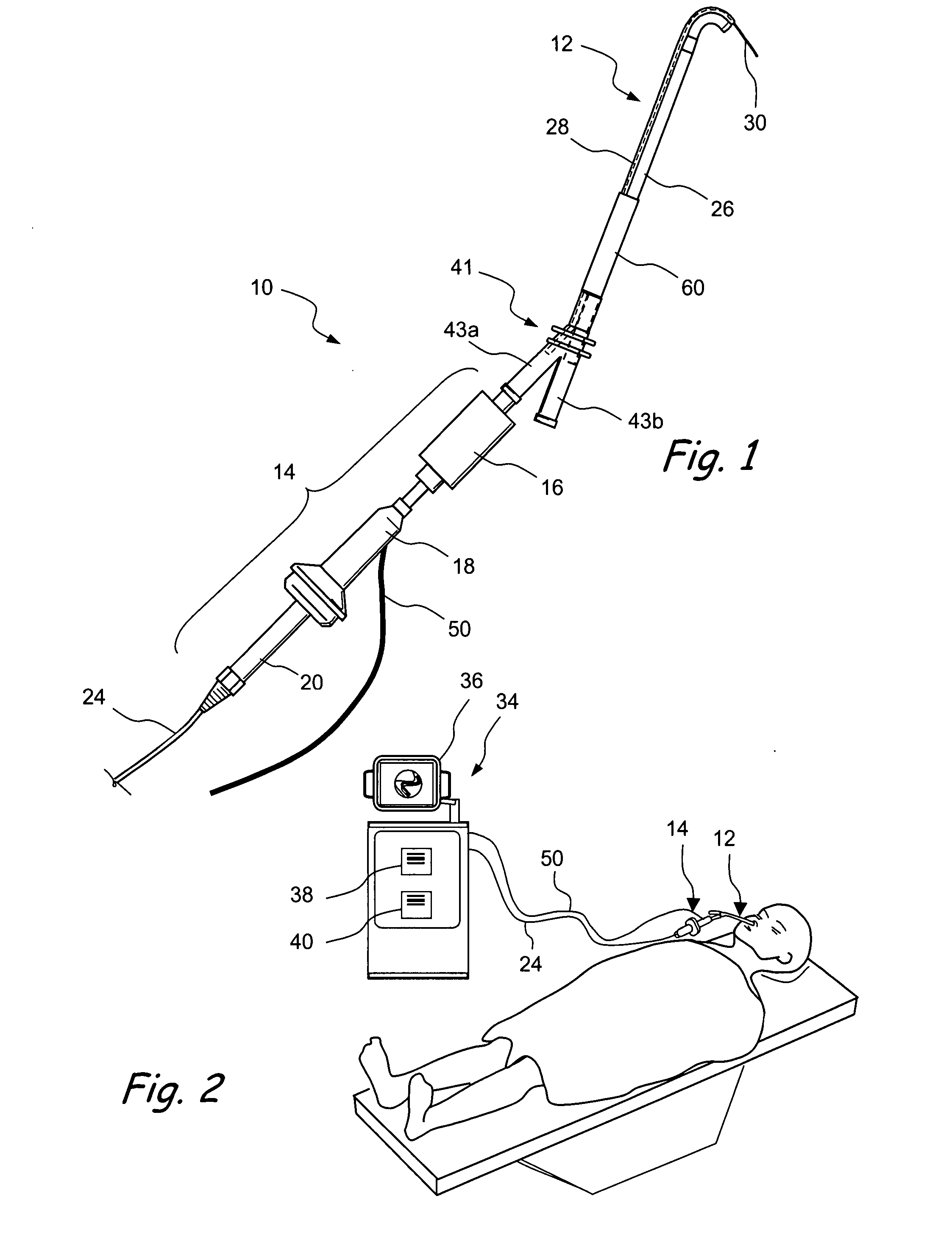
[0010] A beneficial aspect of the present invention is to allow a user to be able to see an adjustable view, with an endoscope, that is generally aligned with the same axis of movement of the user's working device. This is particularly useful when the axis of movement is at an angle with respect to the axis of entry into the patient. This aspect allows the user to see “around the corner” of anatomy that ordinarily would block his / her view and which would therefore require removal in a traditional FESS procedure to allow visualization. This aspect of the invention allows the user to also verify the location of his / her Balloon Sinuplasty™ tools without having to use fluoroscopy or image guidance systems, so that the procedure does not have to be performed in an operating room. Another beneficial aspect of the present invention is that it enables a reduction in the amount of fluoroscopy that needs to be performed by the user doing the procedure, resulting in a reduction in radiation exposure to the user and the patient.
[0011] Another beneficial aspect of the present invention is that it allows a user to hold a tool with an endoscope attached or incorporated therein, such that both can be held with one hand while allowing the user to manipulate another tool with the other hand, thereby eliminating the need for an assistant.
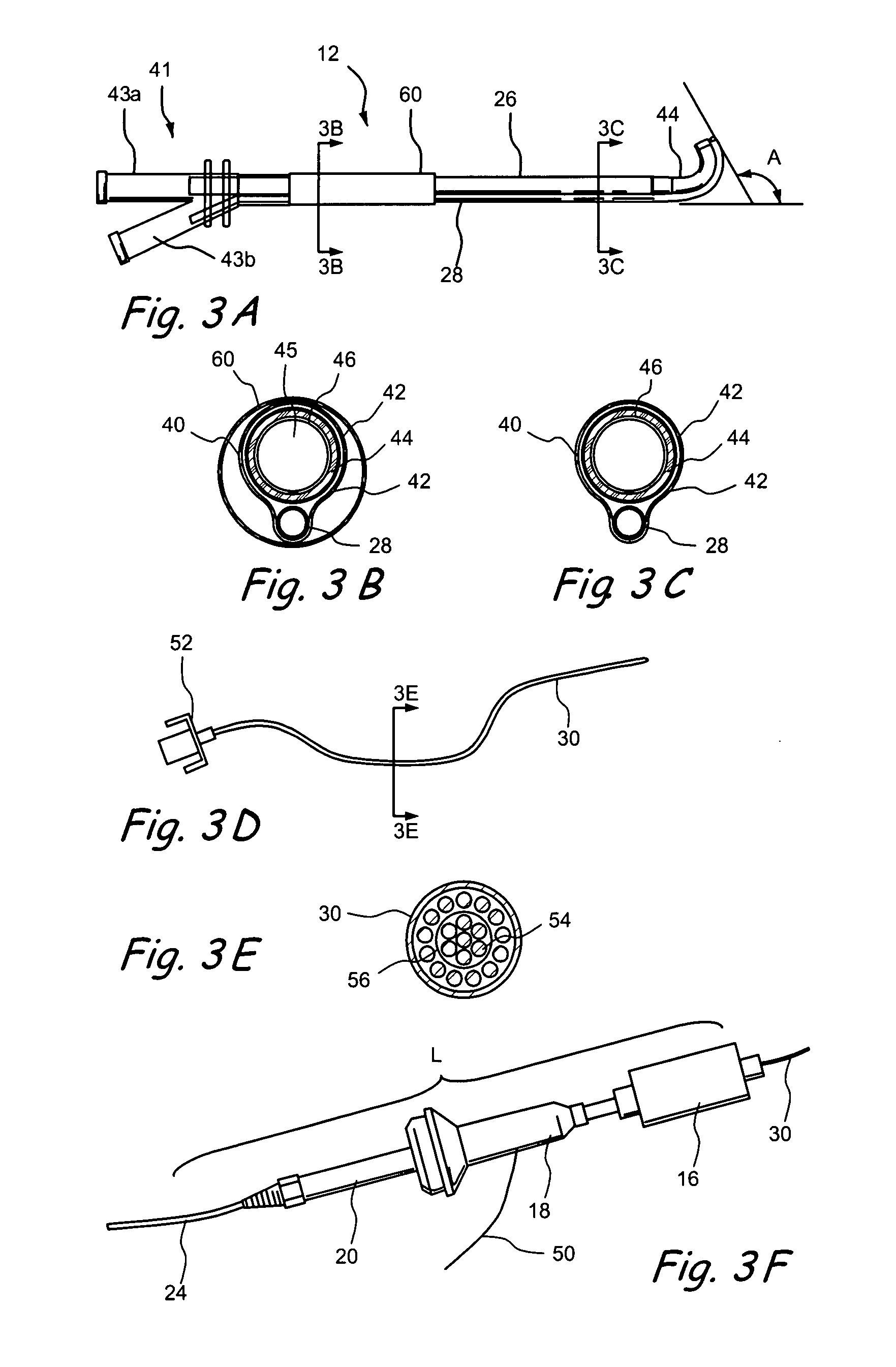
[0012] Another aspect of the invention is a disposable, flexible endoscope that is inexpensive enough for the user to dispose of after ten uses or less, or even after a single use, because the expensive optics that are normally present in the proximal end portion of a conventional flexible (or rigid) endoscope have been relocated in the present embodiments to a re-usable coupler. Also, steerability elements that are normally present in a conventional flexible endoscope have been removed in the present embodiments. Importantly, in at least one embodiment, the entire diameter of the flexible endoscope has an outer diameter of about 0.035 inches or less, so that interventional devices such as a dilatation catheter can be loaded onto and passed over the flexible endoscope. At least one embodiment of the present invention allows the user to load and remove the flexible endoscope from a curved tool, even one having an acute angle bend therein, without breaking or damaging the lens and / or fibers in the endoscope.
[0016] Still further in accordance with the present invention, there is provided a guide system and method wherein a translucent body (e.g., a flexible guidewire tip) is mounted on the distal end of a guide member. An elongate scope is engageable with the translucent body such that light will be cast from the scope, through the translucent body and images will be received by the scope through the translucent body. In this manner, the scope is useable to view an area adjacent to the elongate guide tip, thereby facilitating advancement of the elongate guide tip to a desired location within the body of a human or animal subject. After the elongate guide tip has been advanced to or near the desired location, a working device (e.g., a catheter or other device useable to perform a diagnostic or therapeutic task) is then advanced over the endoscope, translucent member and guide tip. In this manner, the endoscope, translucent member and guide tip combine to perform a function of a continuous guidewire.
[0017] Still further in accordance with the present invention, there is provided another guide system and method wherein an elongate guide member (e.g., a flexible guidewire tip) is attached to and extends from the distal end of a rigid or flexible catheter having a side opening. An endoscope is advanceable out of the side opening of the elongate catheter and useable, when so advanced, to view an area adjacent to the elongate guide tip, thereby facilitating advancement of the elongate guide tip to a desired location within the body of a human or animal subject. Thereafter, the endoscope may be retracted back into the catheter and a working device (e.g., a catheter or other device useable to perform a diagnostic or therapeutic task) is then advanceable over the catheter and guide member. In this manner, the catheter and the guide member combine to perform the function of a continuous guidewire.

Problems solved by technology

Indeed, in most traditional FESS procedures, if the uncinate process is allowed to remain, such can interfere with endoscopic visualization of the maxillary sinus ostium and ethmoid bulla, as well as subsequent dissection of deep structures using the available rigid instrumentation.

Method used


Image

  • Endoscopic methods and devices for transnasal procedures
  • Endoscopic methods and devices for transnasal procedures
  • Endoscopic methods and devices for transnasal procedures

Examples


Embodiment Construction

[0090] Before the present devices and methods are described, it is to be understood that this invention is not limited to particular embodiments described, as such may, of course, vary. It is also to be understood that the terminology used herein is for the purpose of describing particular embodiments only, and is not intended to be limiting.

[0091] Where a range of values is provided, it is understood that each intervening value, to the tenth of the unit of the lower limit unless the context clearly dictates otherwise, between the upper and lower limits of that range is also specifically disclosed. Each smaller range between any stated value or intervening value in a stated range and any other stated or intervening value in that stated range is encompassed within the invention. The upper and lower limits of these smaller ranges may independently be included or excluded in the range, and each range where either, neither or both limits are included in the smaller ranges is also encom...


PUM


Abstract

Medical devices, systems and methods that are useable to facilitate transnasal insertion and positioning of guidewires and various other devices and instruments at desired locations within the ear, nose, throat, paranasal sinuses or cranium.

Description

CROSS-REFERENCE [0001] This application is a divisional application of application Ser. No. 11 / 647,530, filed Dec. 27, 2006, which claims the benefit of Provisional Application No. 60 / 844,874, filed Sep. 15, 2006, and which is a continuation-in-part application of application Ser. No. 11 / 522,497, filed Sep. 15, 2006, and which is also a continuation-in-part application of application Ser. No. 11 / 193,020, filed Jul. 29, 2005, which is a continuation-in-part application of application Ser. No. 10 / 829,917, filed Apr. 21, 2004; Ser. No. 10 / 944,270, filed Sep. 17, 2004; Ser. No. 11 / 116,118, filed Apr. 26, 2005; and Ser. No. 11 / 150,847, filed Jun. 10, 2005. Each of the aforementioned applications are hereby expressly incorporated by reference herein, in their entireties, and to which application we claim priority under 35 USC § 120 and 35 USC § 119, respectively. [0002] This application also claims the benefit of U.S. Provisional Application No. 60 / 844,874, filed Sep. 15, 2006, which appl...

Claims


Application Information

Patent Timeline
Patent Type & Authority Applications(United States)
IPC IPC(8): A61B1/06
CPCA61B1/00135A61B1/00154A61B1/0051A61B1/01A61B1/07A61B1/233A61B1/0607A61B17/3421A61B2017/003A61B2017/246A61B2017/3447A61B1/0014A61B17/24A61B1/044A61M29/02
Inventor GOLDFARB, ERICMORRISS, JOHNCHANG, JOHN Y.
Owner ACCLARENT INC
Why Eureka
Try Eureka