
Hand power tool

a technology of hand power and hand, applied in the field of hand power tools, can solve the problems of fatigue in the user's hand and impair health, and achieve the effect of varying the initial tension of the damping elemen

Inactive Publication Date: 2007-12-27
ROBERT BOSCH GMBH
View PDF35 Cites 29 Cited by
  • Summary
  • Abstract
  • Description
  • Claims
  • Application Information

AI Technical Summary

Benefits of technology

[0007]The damping of vibration that is generated in operation of the hand power tool is achieved by providing that the inner housing and the outer housing are decoupled from one another by at least one damping element in the interstice between the inner housing and the outer housing. All the connections between the inner housing and the outer housing are embodied in vibration-damping fashion. The improved vibration properties of the hand power tool of the invention enhance the user-friendliness of the hand power tool.
[0012]A damping element of an elastic material may have various shapes. For instance, it may be annular, so that it is located in a transverse axis of the hand power tool, extending all the way around over the circumference between the inner housing and the outer housing. It may also be striplike, for instance, and may be located in the interstice, in the longitudinal direction of the hand power tool. A damping element of an elastic material may also be embodied in profiled form, to increase the vibration absorption. Thus the damping element may have channels, for instance, or maybe or be folded multiple times in either the longitudinal or the transverse direction of the hand power tool, resulting for instance in a rectangular, zigzag-shaped or other cross section of the damping element.
[0014]Instead of a separate damping element that is located between the inner housing and the outer housing, the damping element may also be embodied integrally with the inner housing or with the outer housing. In particular, the damping element then forms a spring element which may be integrally molded onto the inner housing or the outer housing, for instance in the form of a tonguelike protrusion. Spring elements of that kind have a supporting function, on the one hand, and stop and compression functions on the other. If a spring element of this kind is formed integrally onto the inner housing in one piece, for instance, then its free end rests on the inner face, in other words, the face toward the inner housing, of the outer housing. Conversely, such a spring element may be formed integrally in one piece onto the outer housing, and its free end may rest on the outer face, that is, the face toward the outer housing, of the inner housing. Another damping element embodied in one piece with the inner housing or with the outer housing is a detent element, which establishes a detent connection of the inner housing and the outer housing. A detent element may likewise have elastic properties that are capable of accomplishing vibration damping.
[0017]A honeycomblike structure of the damping cushion furthermore has the advantage that even if individual honeycomb elements are damaged, the damping action of the entire damping cushion is still not lost. A further advantage of a fluid-, in particular gas-, filled damping cushion is the adjustability of the damping properties of the damping cushion. With the aid of a comparatively simple construction, the damping cushion can be embodied in such a way that the pressure in the damping cushion, and thus the damping action, is adjustable. For that purpose, the damping cushion may for instance be equipped with a valve, by way of which the pressure in the damping cushion can be adapted, for instance to the particularly application.

Problems solved by technology

The vibration is transmitted to the user of the electrical tool via the handle and causes fatigue in the user's hand.
Relatively long-term work with severely vibrating electrical tools can even impair health.

Method used


Image

  • Hand power tool
  • Hand power tool
  • Hand power tool

Examples


Embodiment Construction

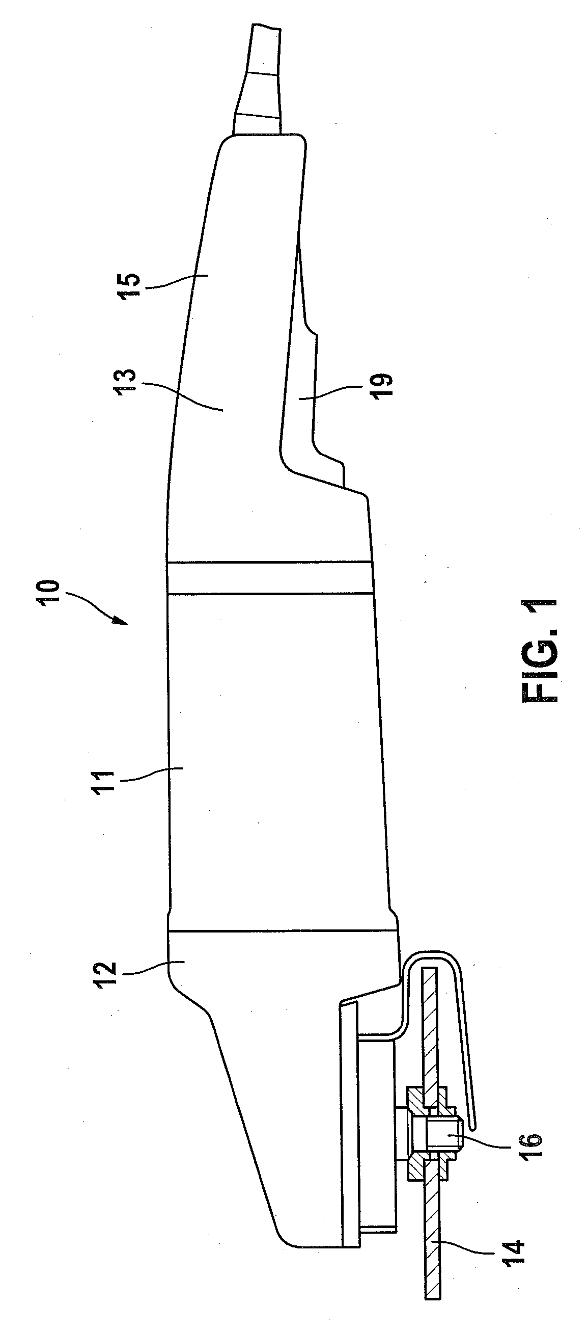
[0045]The right-angle power sander 10 shown schematically in FIG. 1 represents one embodiment of the hand power tool of the invention. In the embodiment shown, the right-angle power sander 10 includes three housing parts: a first housing part 11 for receiving an electric motor (not shown), among other elements; a second housing part 12 for receiving a gear (not shown), among other elements; and a third housing part 13, which is embodied as a handle 15. A drive shaft that can be driven by an electric motor is coupled to a driven shaft 16, via a gear that comprises a driving gear wheel and a driven gear wheel. A sanding wheel 14 is located on the driven shaft 16 in a manner fixed against relative rotation. The electric motor is switched on and off by the user via an ON / OFF switch 19.

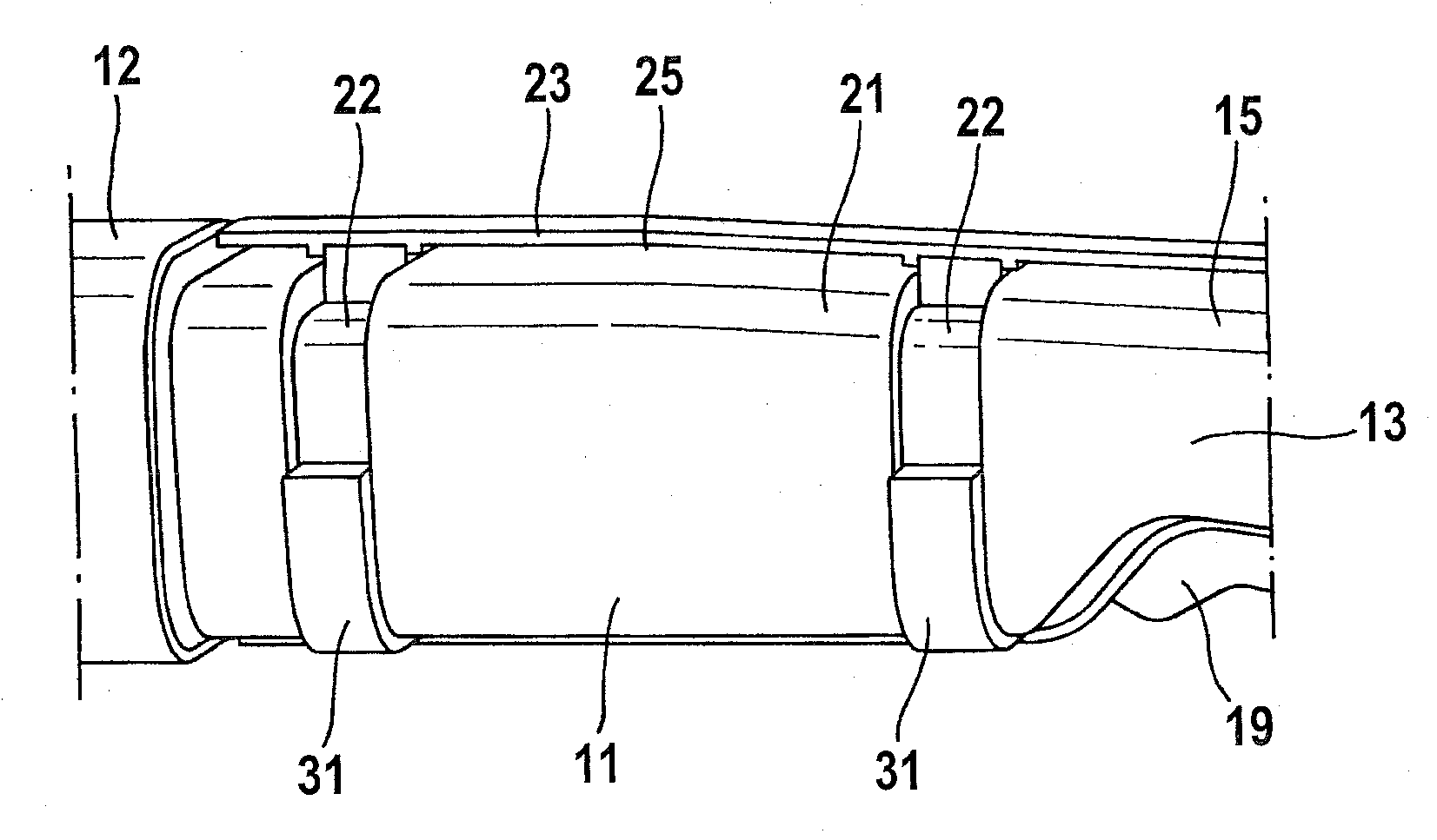
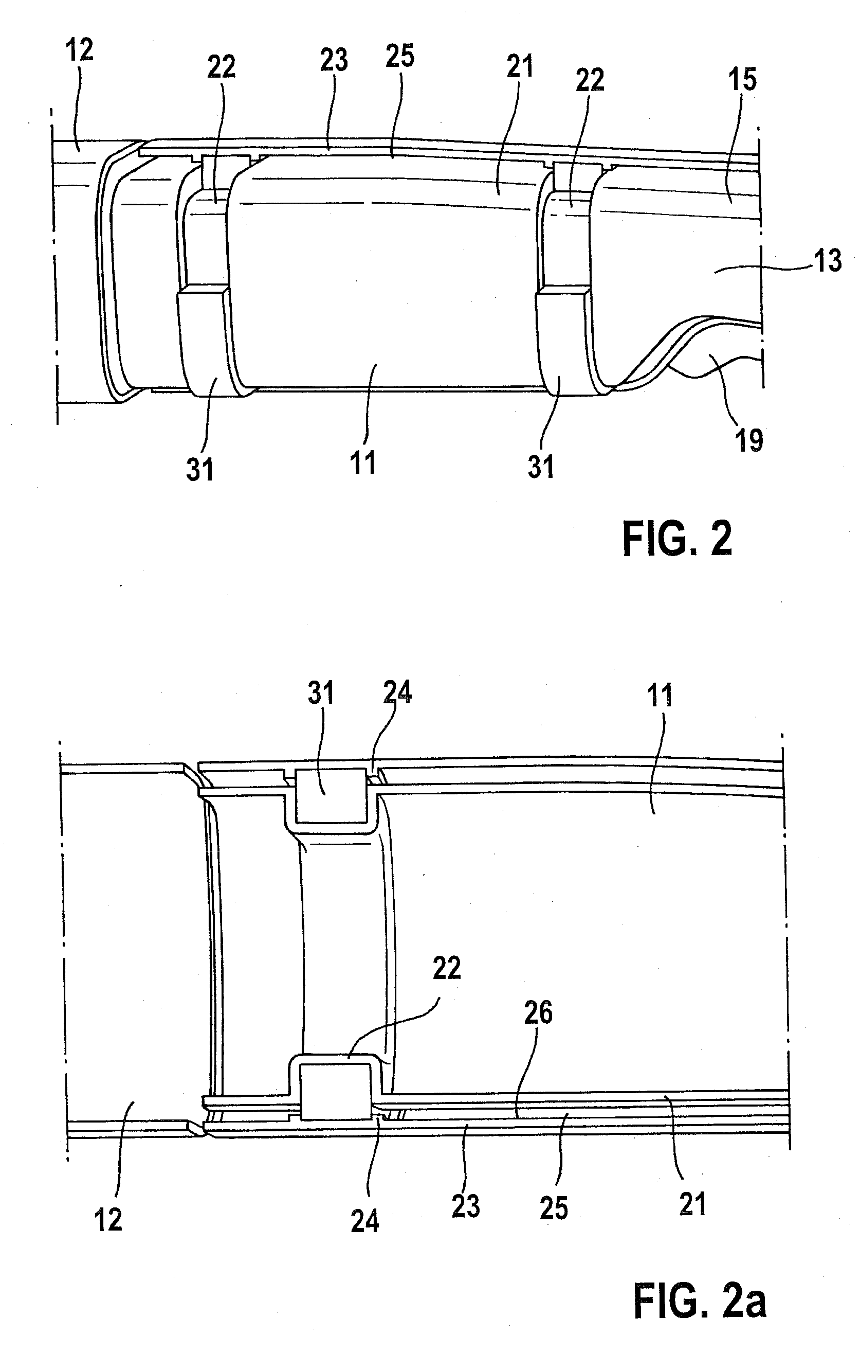
[0046]FIG. 2 shows a schematic detail of the right-angle power sander 10 of FIG. 1. The first housing part 11 is embodied in one piece with the third housing part 13 that is embodied as a handle 15. The ho...


PUM


Abstract

In a hand power tool having a housing which at least in part comprises an inner housing and an outer housing, and in which the inner housing and the outer housing are spaced apart from one another, at least one damping element is provided between the inner housing and the outer housing, so that the inner housing and the outer housing are decoupled from one another.

Description

CROSS-REFERENCE TO A RELATED APPLICATION[0001]The invention described and claimed hereinbelow is also described in German Patent Application DE 102006027774.0 filed on Jun. 21, 2006. This German Patent Application, whose subject matter is incorporated here by reference, provides the basis for a claim of priority of invention under 35 U.S.C. 119(a)-(d).BACKGROUND OF THE INVENTION[0002]The invention is based on a hand power tool.[0003]In work with electrical tools, such as right-angle sanders, drills, and drill hammers, more or less severe vibration occurs, which is engendered, among other factors, by the imbalance of the masses, rotating at high speed, of the motor, gear, tool inserts, and so forth, and by the machining of workpieces. The vibration is transmitted to the user of the electrical tool via the handle and causes fatigue in the user's hand. Relatively long-term work with severely vibrating electrical tools can even impair health.[0004]From German Patent Disclosure DE 40 00 ...

Claims


Application Information

Patent Timeline
Patent Type & Authority Applications(United States)
IPC IPC(8): B25D17/00
CPCB25D17/043B25D17/24B25D17/245B25F5/006B25D2250/245B25D2250/381B25D2250/121
Inventor BOHNE, ULRICHLAMPRECHT, JUSTUSWIKER, JUERGENSAUR, DIETMARKUHNLE, AXELTIEDE, STEFFENLEMMEL, JOERGSCHADOW, JOACHIMSCHOMISCH, THOMASMAUTE, JOERG
Owner ROBERT BOSCH GMBH
Learn More