Glow plug having built-in sensor

a technology of built-in sensors and glow plugs, which is applied in the direction of mechanical equipment, machines/engines, light and heating apparatus, etc., can solve the problems of difficult maintenance or reduction of the difficult to increase the outside diameter of the glow plug and the grommet, etc., to reduce the noise of the output from the combustion-pressure sensor portion, and reduce vibration

Inactive Publication Date: 2007-12-27
NGK SPARK PLUG CO LTD
View PDF4 Cites 34 Cited by
  • Summary
  • Abstract
  • Description
  • Claims
  • Application Information

AI Technical Summary

Benefits of technology

[0008] The present invention overcomes the above problems, and provides a glow plug having a built-in sensor which is configured such that a sensor connection line(s) and a heater-energizing lead wire extend rearward from the rear end of the glow plug and such that a grommet is used to establish liquid-tight seal and which allows a reduction in diameter of the glow plug while the cross-sectional area of a conductor of the heater-energizing lead wire is increased.

Problems solved by technology

Therefore, increasing outside diameter is difficult for a glow plug and a grommet.
That is, for a glow plug having a built-in sensor configured such that a sensor connection line(s) and a heater-energizing lead wire extend rearward from the rear end of the glow plug and such that a grommet is used to establish liquid-tight seal, it is difficult to maintain or reduce the diameter of the glow plug while the cross-sectional area of a conductor of the heater-energizing lead wire is increased.

Method used


Image

  • Glow plug having built-in sensor
  • Glow plug having built-in sensor
  • Glow plug having built-in sensor

Examples


embodiment 1

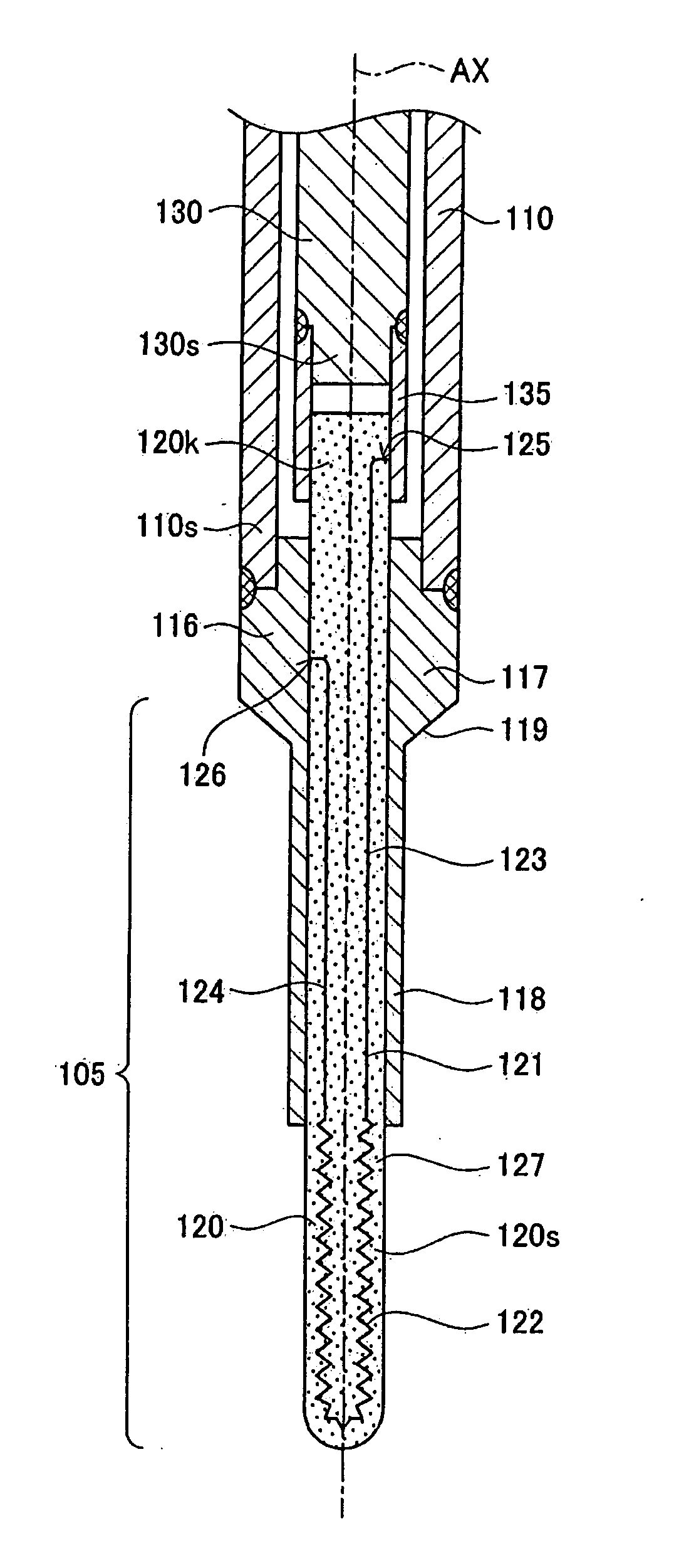
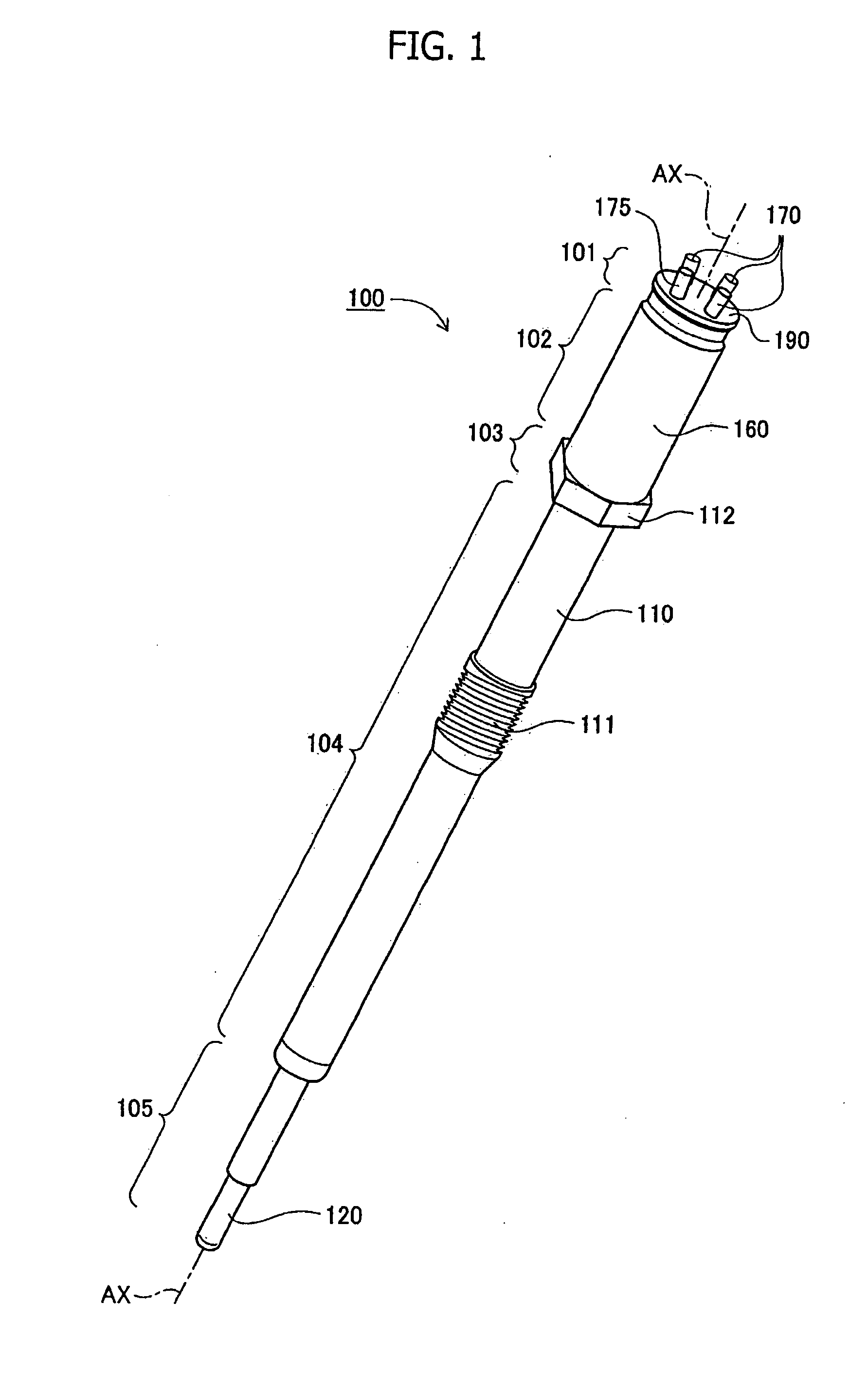
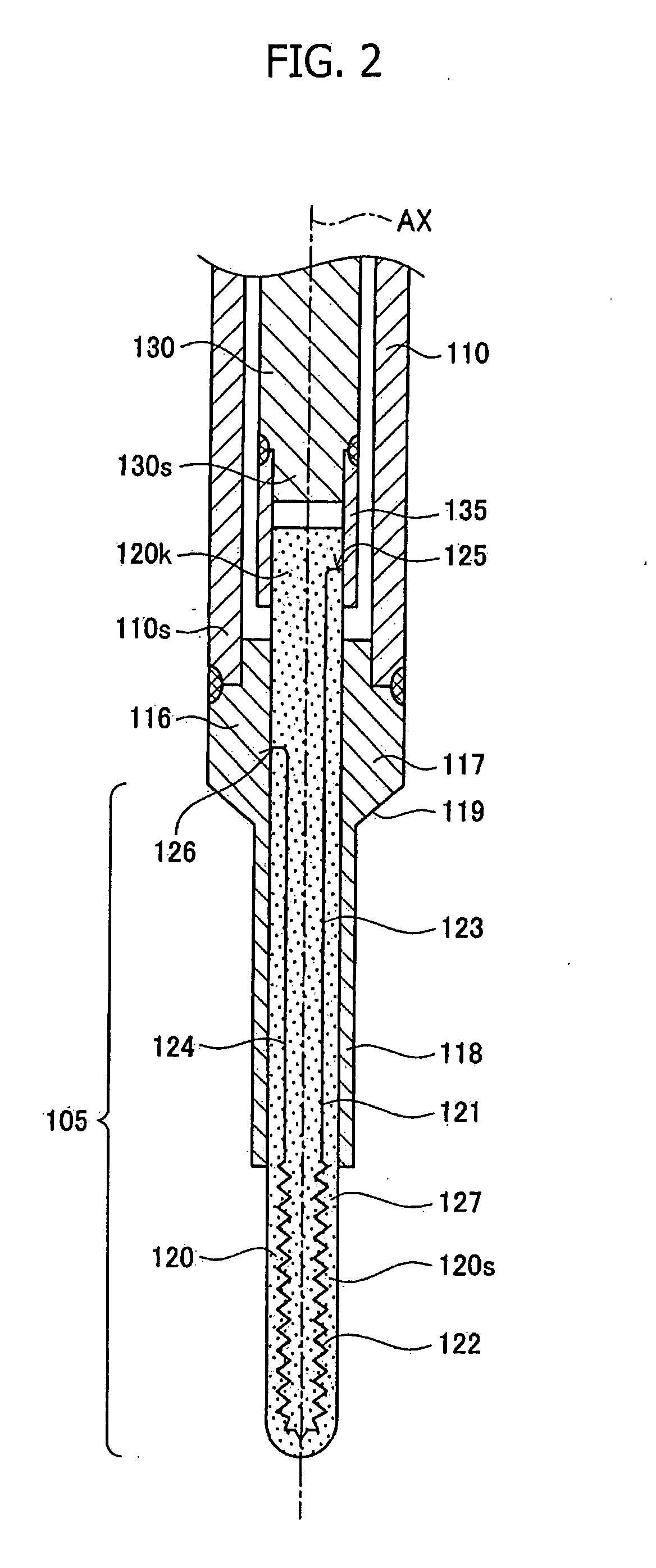
[0054] An embodiment of the present invention will be described with reference to FIGS. 1 to 5. FIG. 1 shows an external view of a glow plug having a built-in combustion pressure sensor (hereinafter, may be referred to merely as a glow plug) 100 according to Embodiment 1. The glow plug 100 can generate heat for assisting the start of an internal combustion engine through energization of a heater member 120 and has a sensor portion 140 configured so as to detect variation of combustion pressure of the internal combustion engine.

[0055] The glow plug 100 assumes a shaft-like form extending along an axis AX and includes, from a rear side (upper right side in FIG. 1) to a front side (lower left side in FIG. 1) along the axis AX, a plug rear-end section 101, a sensor-containing section 102, a hexagonal section 103, a plug intermediate-trunk section 104, and a plug front-end section 105.

[0056] The plug rear-end section 101 is located most rearward in the glow plug 100 and encompasses a g...

embodiment 2

[0112] A glow plug having a built-in combustion pressure sensor 200 according to Embodiment 2 will next be described with reference to FIGS. 6 to 10. Embodiment 1 described above uses the piezoelectric elements 142 and 147 to detect combustion pressure. The glow plug 200 according to Embodiment 2 differs from Embodiment 1 in that a piezoresistive element is used to detect combustion pressure. Therefore, different features will be mainly described, and description of similar features will be omitted or be brief.

[0113]FIG. 6 shows an external view and the structure of the glow plug 200 according to Embodiment 2. The glow plug 200 also can generate heat at a heater member 220 through energization for assisting the start of an internal combustion engine and has a sensor portion 240 configured so as to detect variation of combustion pressure of the internal combustion engine.

[0114] The glow plug 200 also assumes a shaft-like form extending along the axis AX and includes, from the rear ...


PUM


Abstract

A glow plug includes a heater member; heater power lead wires which extend rearward along an axis and whose conductors electrically communicate with one and of a heater conductor for supply of power; a sensor, portion for detecting the combustion pressure of an internal combustion engine; a sensor connection line connected to the sensor portion and extending rearward along the axis; a housing; a sensor-portion-enclosing tube; and a grommet formed from an insulating rubber-like elastic material., having insertion holes through which the heater power lead wires and the sensor connection line are respectively inserted, the grommet liquid-tightly closing an end portion of the sensor-portion-enclosing tube and liquid-tightly holding the heater power lead wires and the sensor connection line.

Description

FIELD OF THE INVENTION [0001] The present invention relates to a glow plug having a built-in sensor. BACKGROUND OF THE INVENTION [0002] Conventionally known glow plugs used to assist the start of an internal combustion engine include a glow plug having a built-in sensor, which is a combustion pressure sensor for detecting the combustion pressure of an internal combustion engine (refer to Japanese Patent Application Laid-Open (kokai) No. 2005-90954); a sensor for detecting the temperature of a heater of the glow plug; a sensor for detecting ion current (refer to Japanese Patent Application Laid-Open (kokai) No. 10-122114); a sensor for detecting combustion light; or a like sensor. [0003] Meanwhile, a glow plug having a built-in sensor of a certain kind requires not only a lead wire for energizing a heater of the glow plug but also a single or a plurality of sensor connection lines for transmitting an output signal from the sensor and driving the sensor. Such a glow plug having a buil...

Claims


Application Information

Patent Timeline
Patent Type & Authority Applications(United States)
IPC IPC(8): F23Q7/22
CPCF02P19/028F23Q2007/002F23Q7/001
Inventor YAMADA, YUICHIMAEDA, SHUNSUKEHIRABAYASHI, TATSUKIISHIHARA, AKITOYAMADA, TATSUNORI
Owner NGK SPARK PLUG CO LTD
Why Eureka
Try Eureka