
Cook top comprising a glass ceramic plate having an opaque coating and an improved window coating on a display window on an underside of the plate

a technology of glass ceramic plates and opaque coatings, which is applied in the direction of coatings, hot plates, electrical appliances, etc., can solve the problems of easy cracking or scratching of the effect pigment layer, noticeably scattered light of illuminating means, and undesirable observation of parts in the interior of the cooking range, for example circuit boards

Inactive Publication Date: 2007-12-27
SCHOTT AG
View PDF3 Cites 44 Cited by
  • Summary
  • Abstract
  • Description
  • Claims
  • Application Information

AI Technical Summary

Benefits of technology

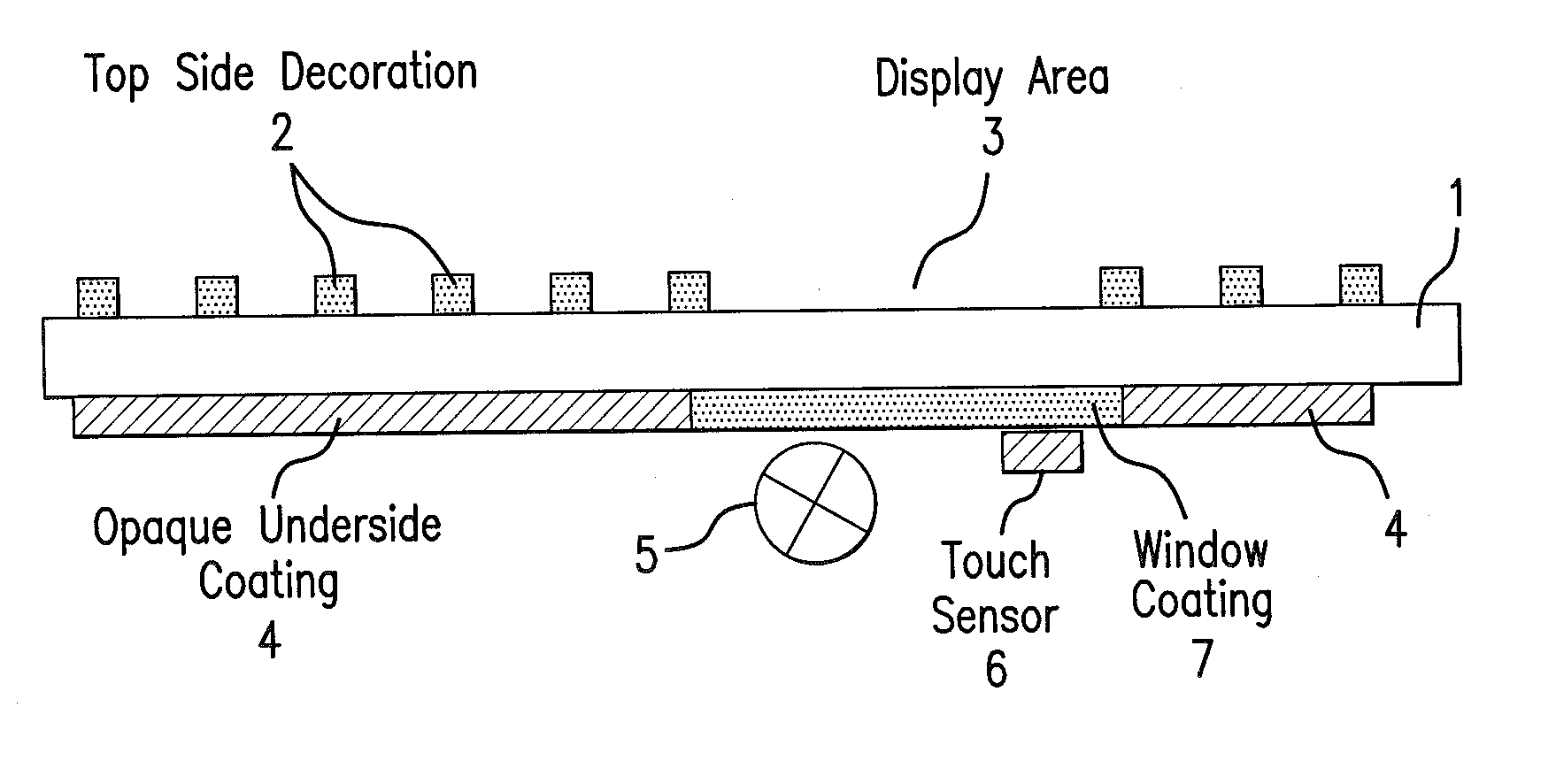
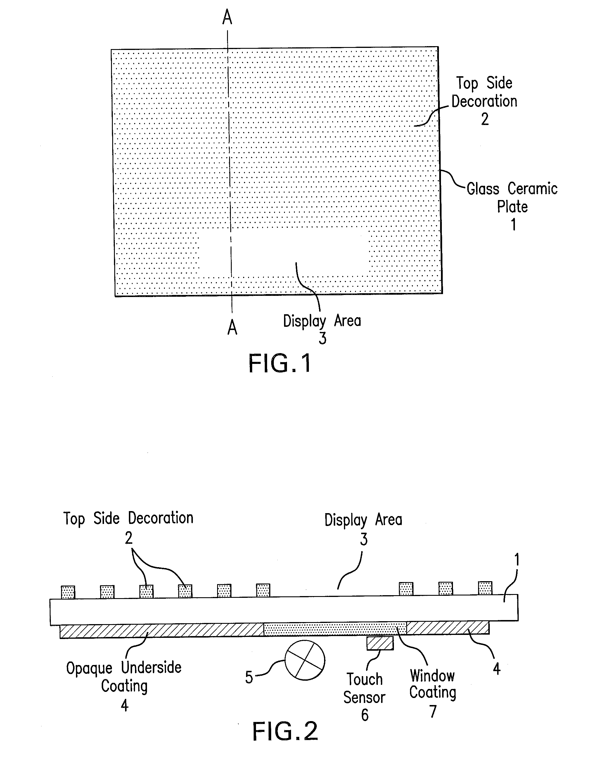
[0039] These objects and others, which will be made more apparent hereinafter, are attained in a cook top comprising a colorless transparent glass ceramic plate with a cooking surface on a top side thereof, which is provided with an opaque coating extending over an underside thereof, except that in at least one window area a window coating is provided on the underside of the glass ceramic plate in place of the opaque coating.
[0040] Accor

Problems solved by technology

The observation of parts in the interior of the cooking range, for example circuit boards, is undesirable for aesthetic reasons.
However the underside coating of the display area with an effect pigment layer has the disadvantage that the effect pigment layer can easily crack or scratch because of the absence of the black covering layer during transport or assembly of the cooking range.
Furthermore the light of illuminating means is noticeably scattered by the effect pigments, because the pigments are a few micrometers in size so that the display device does not have sharp edges and thus appears to be blurry.
Because of the great scattering the illuminating devices are not clearly detectable.
Display windows with effect pigment layers can thus be a safety hazard because their poorly readable displayed values in cases in which display devices that indicate the heating stage are arranged under them.
Often colored glass ceramic plates have nubs or bumps on their underside, which can lead to distortion of the display device.
Since the known noble metal coatings nearly completely block light of wavelengths 400 to 450 nm, they have the disadvantage that they are unsuitable for violet or dark blue illuminating devices.
Because the known noble metal coatings have greatly varying transmittances for visible light, which has wavelengths from 400 to 750 nm, they are hardly suitable for multi-color displays, i.e. displays that use many different color shapes for display of information.
When the known noble metal coatings are used to form the window for a multi-color display, the display may appear imbalanced in regarding to the intensities of the individual colors because of the wavelength dependent varying transmission of these noble metal coatings.
The difference in the intensities of the designated colors, especially the intense red, for which the human eye is most sensitive, could produce an unpleasant impression during operation of the cook top.
The currently used noble metal coatings impair the display of colored information in both processes.
An additional disadvantage of the window of the commercial glass ceramic plates providing a cooking surface is that the display has very small dark areas or spots (FIG. 6a, FIG. 10).
In summary the known solution for coating a window area or display area provided on a colored, transparent, smooth-surfaced (especially both sides) glass ceramic plate does not provide satisfactory uniform light transmission in the visible range and does not provide acceptable clarity of displayed information produced by a display device below the window area.

Method used


Image

  • Cook top comprising a glass ceramic plate having an opaque coating and an improved window coating on a display window on an underside of the plate
  • Cook top comprising a glass ceramic plate having an opaque coating and an improved window coating on a display window on an underside of the plate
  • Cook top comprising a glass ceramic plate having an opaque coating and an improved window coating on a display window on an underside of the plate

Examples


example

Black Display Paint (with Small Electrical Conductivity)

[0085] The top side of a smooth (both sides were smooth) colorless glass ceramic plate 1 (about 60 cm deep, 80 cm wide, and 4 mm thick) having a composition according to EP 1 170 264 B1 (Table I, left column) was coated with a ceramic decorative paint according to DE 197 21 737 C1 in a regular point pattern up to a rectangular window area 3 for the display. The coated glass ceramic plate 1 was then ceramicized.

[0086] Subsequently the commercially obtained noble metal preparation GPP 4510 / S (HERAUS, Hanau) was applied to the underside of the ceramicized glass ceramic plate by means of screen-printing (140-31 mesh), except that the display area 3 was left uncoated. This coating 4 was dried for about 3 hours at 20° C. Then the display area 3 was coated with noble metal preparation GPP 010106 (HEREAUS, Hanau) also by screen-printing (140-31 mesh) to form the window coating 7 in the display area. The noble metal preparations were...


PUM

PropertyMeasurementUnit
Fractionaaaaaaaaaa
Fractionaaaaaaaaaa
Fractionaaaaaaaaaa

Abstract

The cook top includes a colorless transparent glass ceramic plate, which is provided with an opaque coating extending over its underside, except that in at least one window area a window coating is provided on the underside of the glass ceramic plate area instead of the opaque coating. In order to optimize colored displays arranged under the at least one window area and to facilitate the use of capacitive touch sensors, the window coating is a burned-in noble metal preparation with an electrical surface resistance of 1 MΩ / □ and in the at least one window area the glass ceramic plate coated with the window coating has a transmission in a range from 1.0 to 21.0% and a light scattering in a range of from 0.0 to 1.0% for visible light with wavelengths of from 400 nm to 750 nm.

Description

CROSS-REFERENCE [0001] German Patent Application 10 2006 027 739.2-45 filed on Jun. 16, 2006 in Germany describes the invention described herein below and claimed in the claims appended herein below and provides the basis for a claim of priority for the instant invention under 35 U.S.C. 119. The disclosure of this German Patent Application is incorporated here by explicit reference thereto. BACKGROUND OF THE INVENTION [0002] 1. The Field of the Invention [0003] The present invention relates to a cook top comprising a colorless glass ceramic plate with a cooking surface on a top side thereof, which is provided with an opaque coating on an underside thereof, but which has at least one window area. The opaque coating is omitted in the at least one window area, which is provided with a special coating on the underside of the glass ceramic plate. [0004] 2. Related Art [0005] Modern kitchens typically have a cook top with a glass ceramic plate providing a cooking surface. In order to prev...

Claims


Application Information

Patent Timeline
IPC IPC(8): H05B3/68
CPCC03C8/18C03C17/002C03C2218/365C03C17/10C03C2218/36C03C17/04F24C15/10
Inventor STRIEGLER, HARALDWENNEMANN, DIETMARLUKAS, ANNETTE
Owner SCHOTT AG
Learn More