Multiphase claw-pole type electric rotary machine, cogging torque adjustment system of the same, generator system, and motor system

Inactive Publication Date: 2007-12-27
JAPAN SERVO CO LTD
View PDF5 Cites 11 Cited by
  • Summary
  • Abstract
  • Description
  • Claims
  • Application Information

AI Technical Summary

Benefits of technology

[0012] According to the present invention, the multiphase claw-

Problems solved by technology

Incidentally, in the assembly error of the electric rotary machine, misali

Method used


Image

  • Multiphase claw-pole type electric rotary machine, cogging torque adjustment system of the same, generator system, and motor system
  • Multiphase claw-pole type electric rotary machine, cogging torque adjustment system of the same, generator system, and motor system
  • Multiphase claw-pole type electric rotary machine, cogging torque adjustment system of the same, generator system, and motor system

Examples


first embodiment

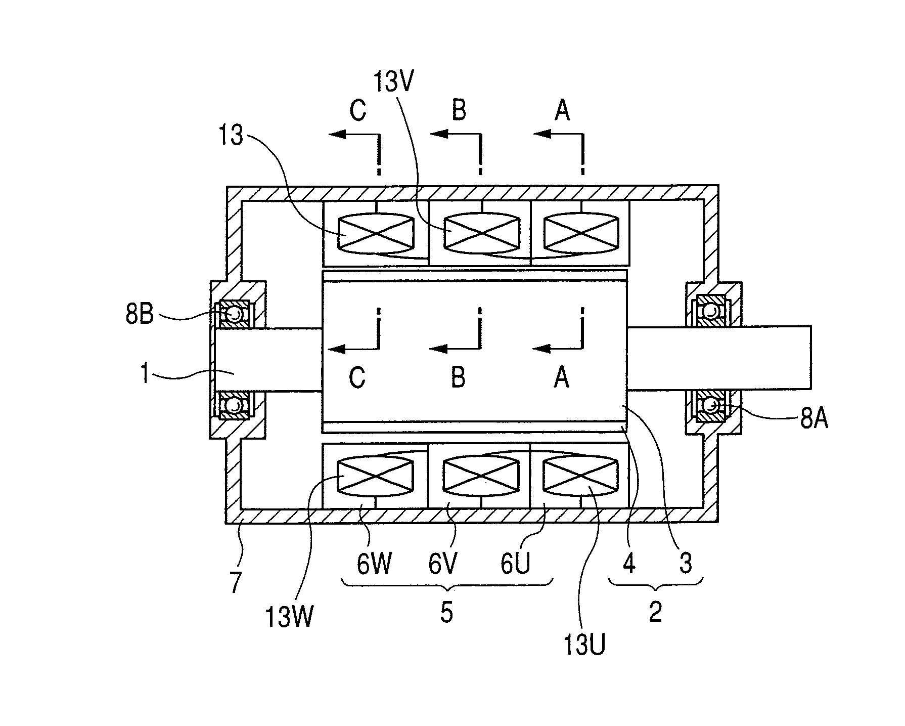
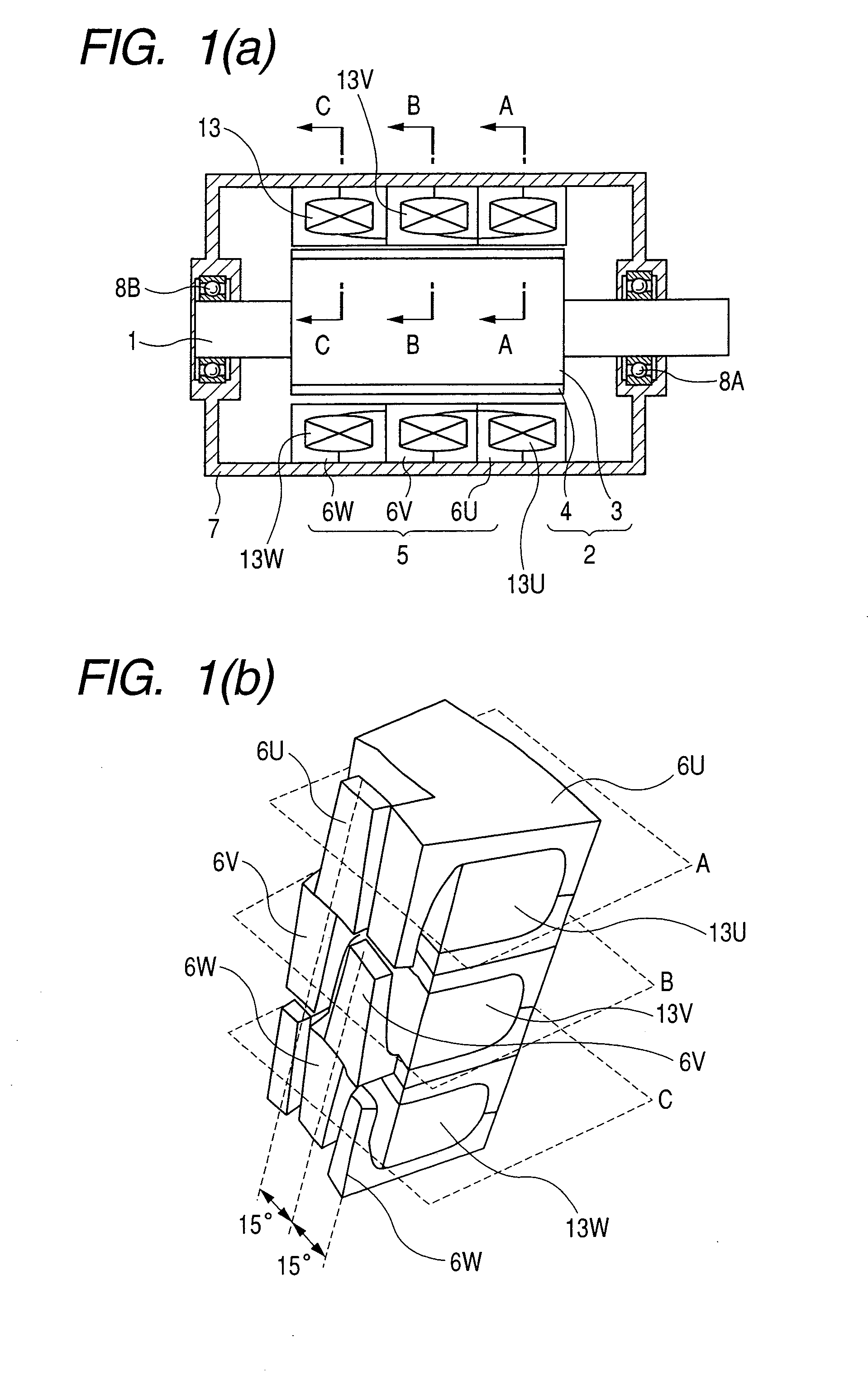
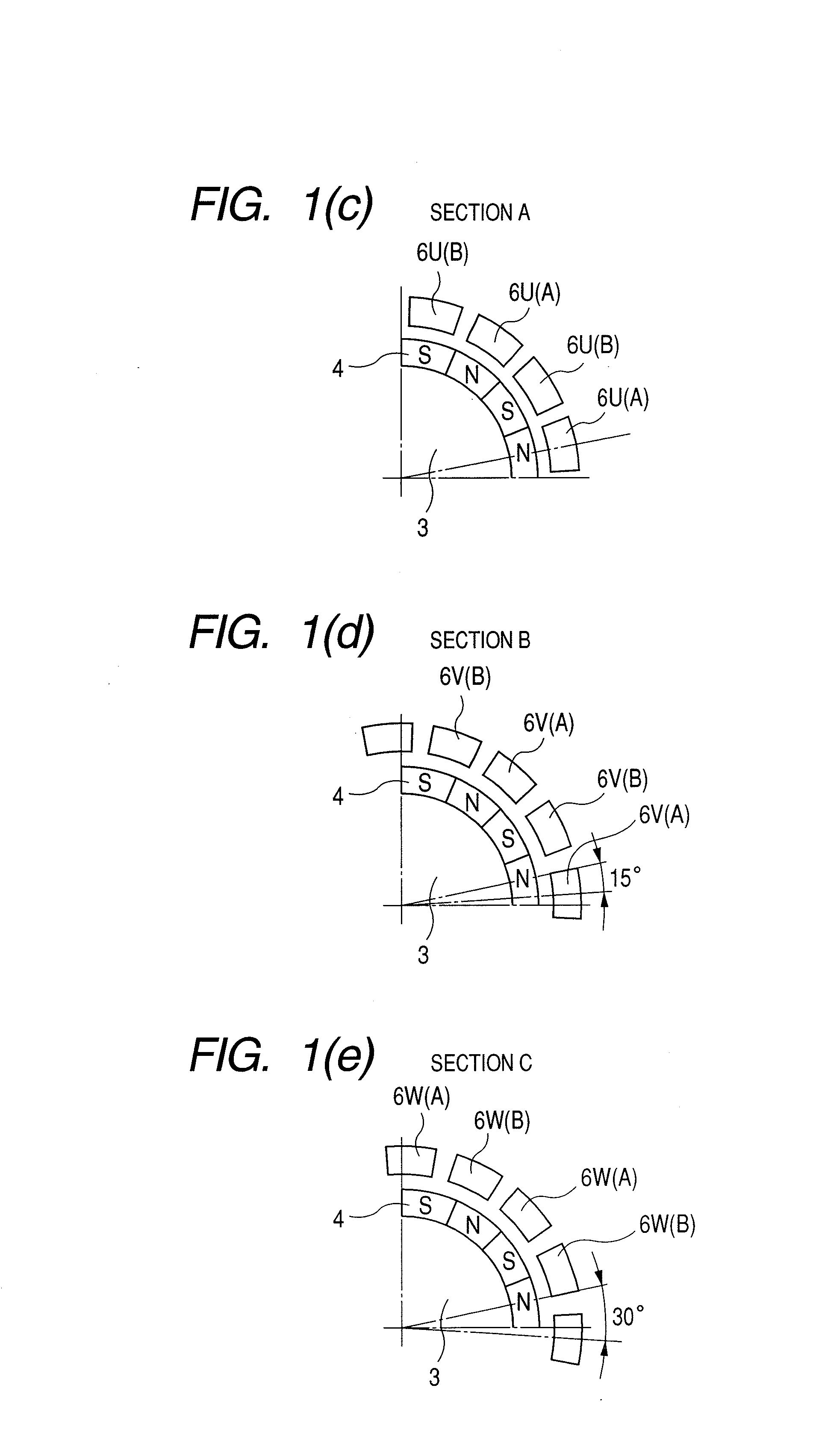
[0021] FIGS. 1(a) to 1(e) are perspective view and cross sections showing the structure of a three-phase claw-pole motor having 16 poles. FIG. 1(a) shows a sectional structure of the motor. A rotor 2 of the motor in the embodiment has a ring magnet structure in which a cylindrical rotor core 3 provided with 16 magnet poles 4 is fixed to a shaft 1 by a method of bonding or the like. Both ends in the axial direction of the rotor 2 are rotatably held by bearings 8A and 8B held in a housing 7. A stator 5 is held in the housing 7 and its inner surface faces an outer surface of the rotor 2 with a gap therebetween. The stator 5 of the motor has a structure in which phases are independent of each other. Respective stator units of phases A (u-phase), B (v-phase), and C (w-phase) are disposed in the axial direction, thereby constructing a three-phase motor. Each of multiple-phase stator unit A, B, and C comprises a pair of complementary-opposed claw pole core blocks 6 (6U, 6V, 6W) and a ring-...

second embodiment

[0030] The structure of the multiple claw-pole motor capable of performing the adjustment of the cogging torque after assembly will now be detailed in FIGS. 6(a) to 6 (f). FIG. 6 (a) is a longitudinal section of a three-phase claw-pole motor. The structure of the motor is similar to that of the claw-pole motor shown in FIGS. 1(a) to 1(e) except for the adjusting function for cogging torque. In the claw-pole motor, both end faces in the axial direction of each stator core block 6 (6U, 6V, 6W) are provided with spigot-recess 24 (spigot 24a, recess 24b) for realizing the rotating function without shifting the axis center of stator core block to enable rotatably adjust for multiphase stator units after assembly of a motor. FIG. 6(b) shows a concrete structure on one phase stator unit example. The spigot (ring shaped-projection) 24a is formed in one of end faces in the axial direction of the stator core block 6 of one phase in a ring shape, and a recess 24b is formed on the other end fac...

third embodiment

[0034] Next, an embodiment of a motor or a generator system applying the mechanism capable of rotating the above-mentioned stator core blocks 6 (6U, 6V, 6W) will be described. For example, as stated above, when changing positions of the stator core blocks 6 in each phase, the electric characteristics of the motor or generator can be changed. Consequently, when applying the above-mentioned stator core rotatable mechanism to generator, the output of the generator, if any, has an excess increase of voltage by increase in the rotational speed of the generator, it is possible to control the output voltage so as to reduce into allowable value by changing positions of the stator cores of multiphase. FIG. 7 is a generator system for generating an electric power by rotation torque of the internal combustion engine 28. In FIG. 7, when the generator output voltage, which is supplied to power generation controller 29 for equipment such as a battery, various control systems and the like, exceeds...


PUM


Abstract

A multiphase claw-pole type electric rotary machine has two or more phases-stator units. The stator units are arranged phase by phase in an axial direction of the electric rotary machine. Each phase stator unit comprises a pair of complementary-opposed claw pole core blocks and a ring-shaped stator coil sandwiched therebetween. The stator units have structures rotatably adjustable independent of each other in their phase positional relations while maintaining concentricity of them after assembly of the rotary machine before being secured.

Description

CLAIM OF PRIORITY [0001] The present application claims priority from Japanese application serial no. 2006-166808, filed on Jun. 16, 2006, the content of which is hereby incorporated by reference into this application. FIELD OF THE INVENTION [0002] The present invention relates to the structure of a multiphase claw-pole type electric rotary machine such as a motor and a generator for use in the industrial, household, and vehicle fields. BACKGROUND OF THE INVENTION [0003] A motor is used as a drive device for converting electric energy in the industrial, household, and vehicle fields to a mechanical output. A claw-pole motor is used for an OA device, a vehicle device, and the like because of its low-cost structure and a simple drive circuit. Usually, the claw-pole motor is used as a two-phase stepping motor as described in Japanese laid-open Patent Application Publication No. H7-227075. Motors are generally classified into a single phase, two phases, and three phases, which are prope...

Claims


Application Information

Patent Timeline
IPC IPC(8): H02K37/14H02K16/02H02K1/12
CPCH02K29/03H02K21/145
Inventor ENOMOTO, YUJIITO, MOTOYAMASAKI, RYOSOOHIWA, SHOJIISHIHARA, CHIO
Owner JAPAN SERVO CO LTD
Why Eureka
Try Eureka