Display device

a technology of a display device and a display screen, which is applied in the field of display devices, can solve the problems of no technology that would improve the bright room contrast in the wavelength band, and achieve the effects of reducing the reflectance rate of outer light incident, improving bright room contrast, and suppressing the reflection of outer ligh

Inactive Publication Date: 2007-12-27
HITACHI CONSUMER ELECTRONICS CORP
View PDF10 Cites 4 Cited by
  • Summary
  • Abstract
  • Description
  • Claims
  • Application Information

AI Technical Summary

Benefits of technology

[0007]An object of the present invention is to improve bright room contrast by suppressing the reflection of outer light.
[0008]In an embodiment of the present invention, an optical filter is provided on the output side of the light from plural kinds of cells that output light with color different from one another. In the optical filter, the penetrable rate of the wavelength band of the light output from the cell with the color having the highest luminescent intensity is set lower than that of the wavelength band of other kinds of cells. For example, when the display device has a red cell that emits red light, a green cell that emits green light, and a blue cell that emits blue light, and the luminescent intensity of the green cell is the highest, the penetrable rate of the wavelength band of the green light is set lower than that of the wavelength bands of the red and blue light. Due to this, it is possible to reduce the reflectance rate of outer light incident on the display. In particular, in a room environment in which artificial lighting is used, it is possible to reduce the reflectance rate of outer light in the wavelength band of the light having a comparatively high luminescent intensity. As a result, it is possible to improve bright room contrast by suppressing the reflection of outer light.
[0009]In another embodiment of the present invention, in a cell with a color having the highest luminescent intensity, luminescent intensity is further increased in order to compensate for the amount of light that will run short when the penetrable rate of an optical filter is reduced. For example, the improvement of luminescent intensity can be realized by applying at least any one of three conditions that (a) the cell width is widened, (b) the area of the transparent electrode is increased, and (c) the phosphor layer of the cell is thickened. Due to this, it is possible to make the luminescent intensity of the light from a cell with a color having the highest luminescent intensity equal to the conventional one at the output surface of the light of the optical filter. Consequently, it is possible to improve bright room contrast by suppressing the reflection of outer light without reducing the brightness of the display. In addition, it is possible to make the intensity ratio of the light from a plurality of kinds of cells equal to the conventional one at the output surface of the light of the optical filter. As a result, it is possible to make the hue, such as white balance, have the same quality as ever before.
[0010]In another embodiment of the present invention, a display device has a red cell that emits red light, a green cell that emits green light, and a blue cell that emits blue light. The luminescent intensity is the highest in the green cell, the next highest in the red cell, and the lowest in the blue cell. The penetrable rate of the light of an optical filter is the highest for the light of the blue wavelength band, the second highest for the light of the red wavelength band, and the lowest for the light of the green wavelength band. The blue cell has a narrow cell width than the red cell in order to reduce the amount of light that will be excessive when the penetrable rate of the optical filter is increased. It is possible to reduce the reflectance rate of outer light most effectively by reducing the penetrable rate and increasing the brightness of the color having a relatively high luminescent intensity, and by increasing the penetrable rate and reducing the brightness of the color having a relatively low luminescent intensity. As a result, it is possible to improve bright room contrast by suppressing the reflection of outer light without reducing the brightness of the display.

Problems solved by technology

Conventionally, however, there has been proposed no technique that would improve the bright room contrast in the wavelength band that overlaps the wavelength band of the light emitted from the display.

Method used


Image

  • Display device
  • Display device
  • Display device

Examples


first embodiment

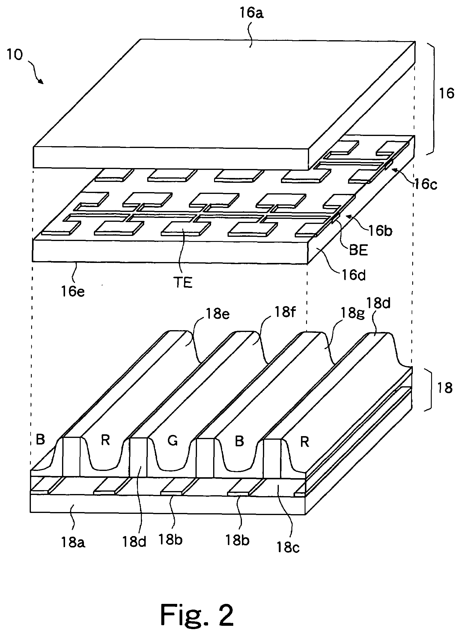
[0058]As described above, in the first embodiment, the penetrable rate of green light emitted from the green cell GC of which the luminescent intensity is the highest relatively is set lower than those of other colors. Due to this, it is possible to reduce the reflectance rate of outer light incident on the side of the front plate 16 of the PDP 10. Artificial lighting such as a fluorescent lamp is often used for lighting in a room in which the PDP device is installed. In general, in artificial lighting, the brightness of green is relatively higher compared to red and blue. Because of this, particularly in a room environment, it is possible to efficiently reduce the reflectance rate of outer light and improve bright room contrast.

[0059]In addition, by further increasing the luminescent intensity of the green cell GC by widening the cell width, it is possible to further reduce the penetrable rate of the green light and improve bright room contrast. The cell width becomes narrow relati...

second embodiment

[0061]FIG. 13 shows the wavelength dependence of the penetrable rate of the optical filter (corresponding to symbol 20 in FIG. 1) and the luminescent intensity of the cell in the The broken line in the figure shows the conventional characteristic and the solid line shows the characteristic of the present invention. In the present embodiment, the luminescent intensity of the blue cell BC with a narrow cell width becomes lower compared to the conventional one. In other words, the blue cell BC has a narrower cell width compared to the red cell RC in order to reduce the amount of light that will be excessive when the penetrable rate of the optical filter is increased. The luminescent intensity of the green cell GC with a wide cell width is higher compared to the conventional one and the luminescent intensity of the red cell RC with the same cell width as the conventional one is the same as the conventional one.

[0062]In the optical filter, the penetrable rate of the green wavelength ban...

third embodiment

[0069]FIG. 17 shows the wavelength dependence of the penetrable rate of the optical filter (corresponding to symbol 20 in FIG. 1) and the luminescent intensity of the cell in the The broken line in the figure shows the conventional characteristic and the solid line shows the characteristic of the present invention. In the present embodiment, the luminescent intensity of the green cell GC with a large electrode area becomes higher compared to the conventional one and the luminescent intensities of the red cell RC and the blue cell BC with the same electrode area as the conventional one are the same as the conventional ones.

[0070]In the optical filter, the penetrable rate of the green wavelength band is reduced compared to the conventional one and the penetrable rates of the red and blue wavelength bands are set to those the same as the conventional ones in accordance with the luminescent intensity of the PDP. Due to this, the brightness of the red, green, and blue light output from ...


PUM


Abstract

An optical filter is provided on the output side of light from plural kinds of cells that output light with colors different from one another. In the optical filter, the penetrable rate of at least a portion of the wavelength band of light output from the cell with the color having highest luminescent intensity is set lower than that of the wavelength band of other kinds of cells. Consequently, the reflectance rate of outer light incident to a display can be reduced. Particularly, in a room environment using artificial lighting, the reflectance rate of outer light can be reduced in the wavelength band of light with relatively high luminescent intensity. Resultingly, bright room contrast can be improved by suppressing the reflection of outer light. Since the penetrable rate of the color with the highest luminescent intensity is reduced, reduction in brightness of the display can be kept to a minimum.

Description

CROSS REFERENCE TO RELATED APPLICATION[0001]This application is based upon and claims the benefit of priority from Japanese Patent Application No. 2006-175672, filed on Jun. 26, 2006, the entire contents of which are incorporated herein by reference.BACKGROUND OF THE INVENTION[0002]1. Field of the Invention[0003]The present invention relates to a display device that displays an image.[0004]2. Description of the Related Art[0005]Generally, in a display device, in order to suppress the reflection of outer light incident on the display and to improve bright room contrast, a filter having a predetermined penetrable rate is arranged on the display surface side of a panel. In addition, a technique has been proposed (for example, Japanese Unexamined Patent Application Publication No. 2003-157017), which improves bright room contrast by reducing the penetrable rate for wavelength bands except for the wavelength band of the light emitted from the display without reducing the brightness of th...

Claims


Application Information

Patent Timeline
Patent Type & Authority Applications(United States)
IPC IPC(8): H01J1/62G09F9/00H01J11/12H01J11/22H01J11/24H01J11/26H01J11/34H01J11/36H01J11/38H01J11/40H01J11/42H01J11/44H01J11/50H04N5/66H04N5/72
CPCH01J1/63H01J11/44H01J11/42H01J11/12G02B5/20
Inventor SASAKI, TAKASHIOTSUKA, AKIRATAKAGI, AKIHIRO
Owner HITACHI CONSUMER ELECTRONICS CORP
Why Eureka
Try Eureka