Circuit for detecting end of life of fluorescent lamp

Inactive Publication Date: 2007-12-27
FAIRCHILD KOREA SEMICON
View PDF9 Cites 14 Cited by
  • Summary
  • Abstract
  • Description
  • Claims
  • Application Information

AI Technical Summary

Benefits of technology

[0019] Briefly and generally, some embodiments of the present invention include a circuit for detecting the end of life of a fluorescent lamp, which effectively detects not only that both electrodes of the fluorescent lamp have been darkened b

Problems solved by technology

However, it is difficult to visually determine whether the lamp life is at the end before its fluorescent materials completely disappear.
If the electrode generates intense heat, the heat may melt a lamp socket connected to the electrode, thereby causing a dangerous situation.
Generally, in the early stage of the end of life of the fluorescent lamp, it is impossible to visually determine whether its brightness has been reduced.
Although this method is adva

Method used


Image

  • Circuit for detecting end of life of fluorescent lamp
  • Circuit for detecting end of life of fluorescent lamp
  • Circuit for detecting end of life of fluorescent lamp

Examples


Embodiment Construction

[0046] Embodiments of the present invention will now be described in detail with reference to the accompanying drawings. The embodiments of the present invention have been disclosed for illustrative purposes only and should not be construed as limiting the scope of the present invention.

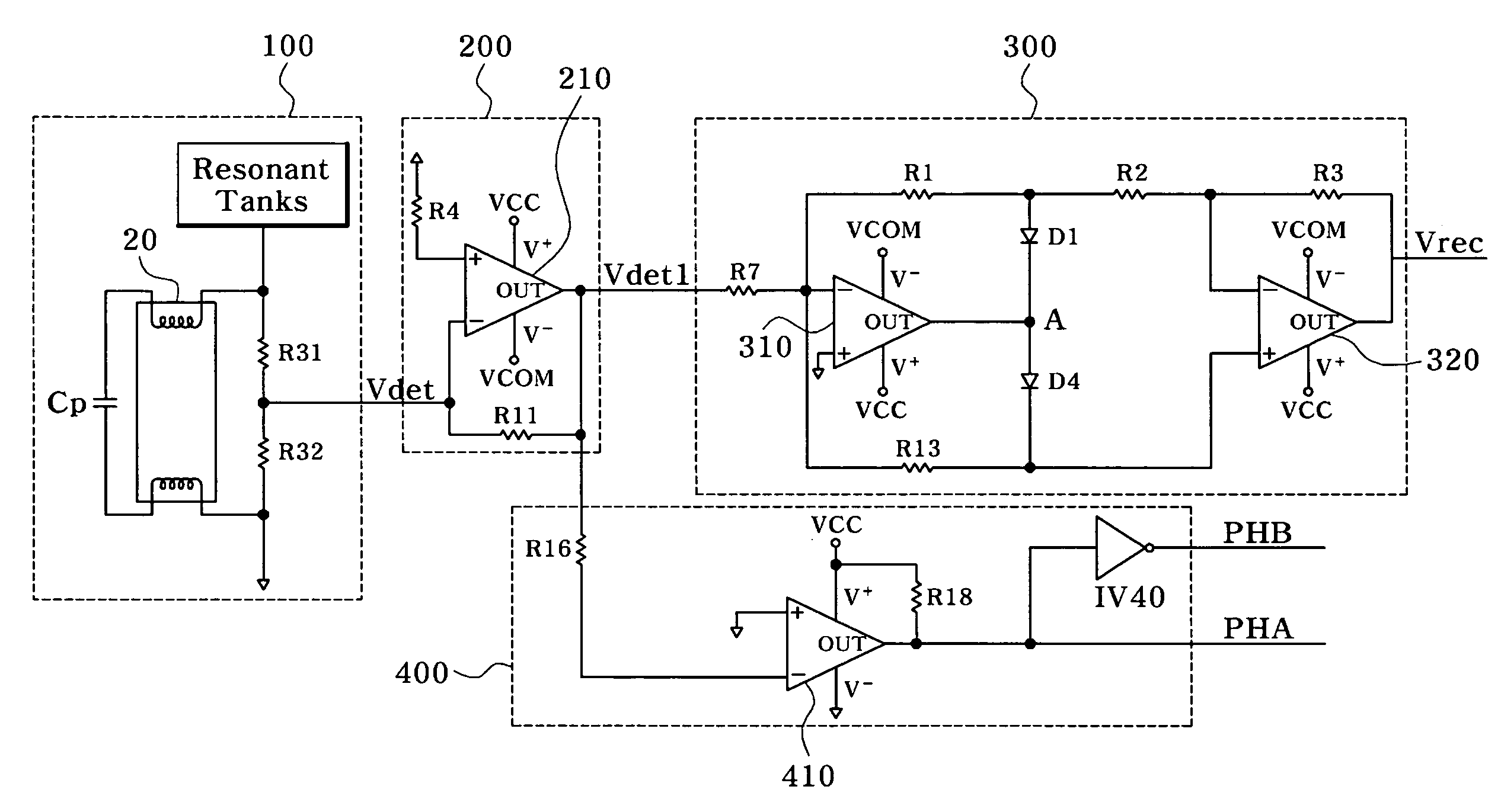
[0047]FIG. 5 illustrates an embodiment of a circuit 50 for detecting the end of life of a fluorescent lamp.

[0048] The circuit 50 can include a ballast 100, a buffer 200, a rectifier 300, a phase detector 400, a signal separator 500, a first maximum level detector 600, a second maximum level detector 650, a first comparison unit 700, a second comparison unit 750, and a controller 800. The buffer 200 can buffer a voltage signal Vdet detected from the ballast 100. The rectifier 300 can rectify a voltage signal.Vdet1, received from the buffer 200, and output a rectified voltage Vrec. The phase detector 400 can detect the phase of the voltage signal Vdet1 and output at least one phase detection signal. ...


PUM


Abstract

A circuit for detecting the end of life of a fluorescent lamp is provided. In this circuit, a rectifier rectifies a voltage signal detected from a ballast. A phase detector detects the phase of the voltage signal and outputs at least one phase detection signal. A signal separator separates the rectified voltage on a phase basis to generate first and second voltage signals in response to the phase detection signal. A first maximum level detector detects the maximum level of the first voltage signal. A second maximum level detector detects the maximum level of the second voltage signal. A first comparison unit compares the first and second maximum levels and detects whether or not the difference is higher than a predetermined allowable level. A controller determines whether or not the fluorescent lamp is at the end of life in response to the detection from the first comparison unit.

Description

CROSS-REFERENCE TO RELATED APPLICATION [0001] This application claims priority to and the benefit of Korean Patent Application No. 10-2006-0048769 filed in the Korean Intellectual Property Office on May 30, 2006, the entire content of which is incorporated herein by reference. BACKGROUND [0002] 1. Field of the Invention [0003] The present invention relates to a circuit for detecting the end of life of a fluorescent lamp, and more particularly to a circuit for detecting the end of life of a fluorescent lamp in an early stage of the end of life so as to effectively protect a ballast, a socket, and relevant circuits of the fluorescent lamp. [0004] 2. Description of the Related Art [0005] If a fluorescent lamp is used for a long time, Barium (Ba) or Strontium (Sr), the material of an auxiliary emitter for thermionic emission coated on an electrode (cathode) at each end of the fluorescent lamp, is absorbed into inner or outer walls of its tube and the amount of material coated on filamen...

Claims


Application Information

Patent Timeline
IPC IPC(8): G01R31/24
CPCH05B41/2985G01R31/44H05B41/295H05B41/285
Inventor LEE, YOUNG-SIKCHO, GYE-HYUN
Owner FAIRCHILD KOREA SEMICON
Why Eureka
Try Eureka