Resonant circuit tuning system with dynamic impedance matching

a tuning system and dynamic impedance technology, applied in the field of electronic tuning systems, can solve the problems of increasing the voltage across the coil, increasing the cost of the circuit to meet the requirements, and a large number of coil turns to reduce the curren

Active Publication Date: 2007-12-27
SENSORMATIC ELECTRONICS CORP
View PDF4 Cites 46 Cited by
  • Summary
  • Abstract
  • Description
  • Claims
  • Application Information

AI Technical Summary

Problems solved by technology

Additionally, the use of a high inductance and high Q LCR circuit results in an increase in the voltage across the coil.
Further, regulatory requirements may limit the amplitude of the output current, which may increase the cost of the circuit to meet the requirements.
However, in high power applications, a high number of coil turns are needed to reduce the current.
These opposing constraints result in a limitation of the amount of magnetic field that may be produced from, for example, an antenna having such an LCR circuit.
This circuit is limited in that the circuit does not allow compensation, for example, for tolerances in antenna coil construction and / or installation environment variations.
Thus, these known circuits for tuning often result in either increased power requirements and / or increased cost.
Further, these known circuits may not perform satisfactorily because of the inability to provide compensation for variations of changes that affect the circuit.

Method used


Image

  • Resonant circuit tuning system with dynamic impedance matching
  • Resonant circuit tuning system with dynamic impedance matching
  • Resonant circuit tuning system with dynamic impedance matching

Examples


Embodiment Construction

[0017]For simplicity and ease of explanation, the invention will be described herein in connection with various embodiments thereof. Those skilled in the art will recognize, however, that the features and advantages of the various embodiments of the invention may be implemented in a variety of configurations. It is to be understood, therefore, that the embodiments described herein are presented by way of illustration, not of limitation.

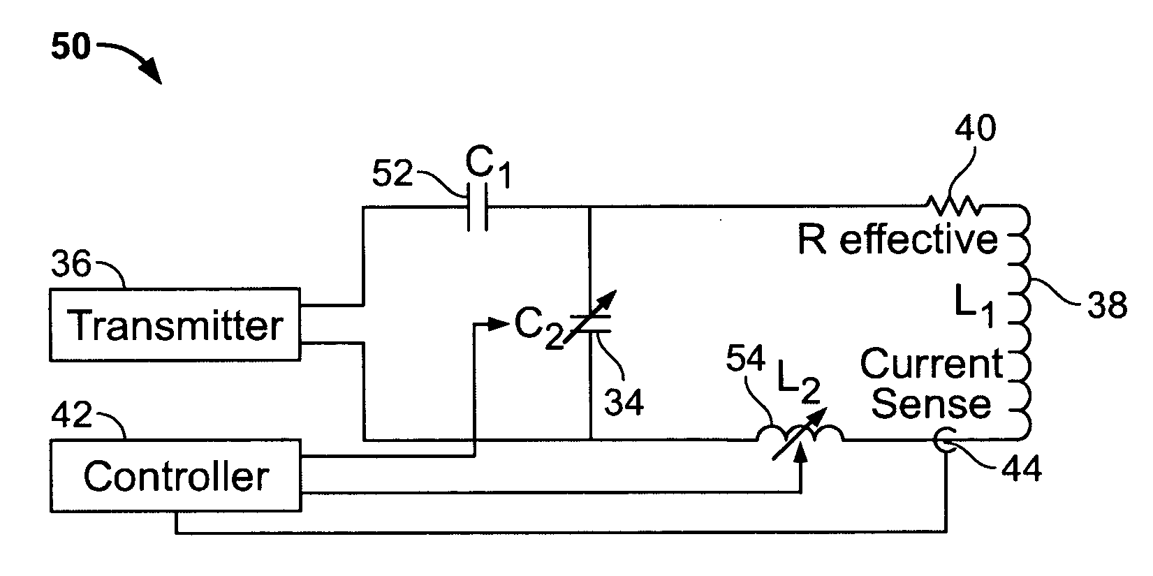
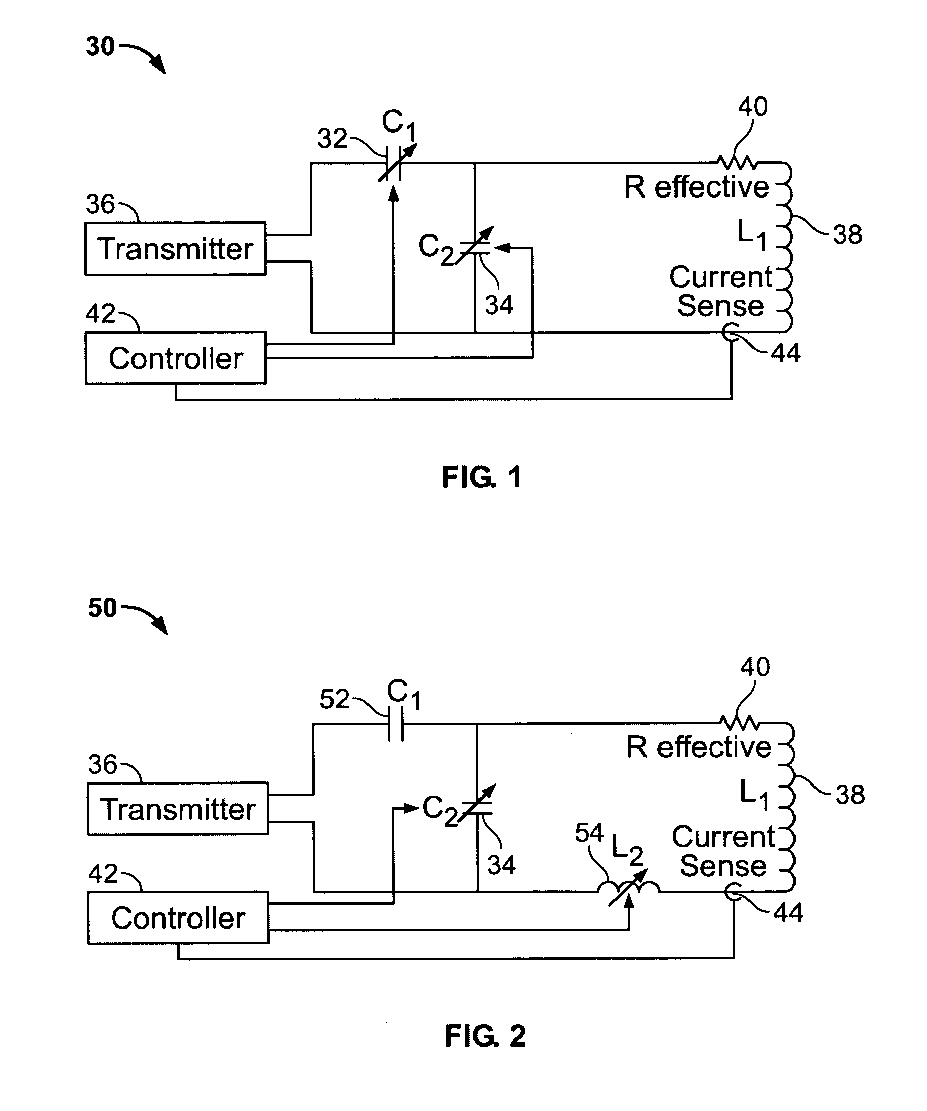
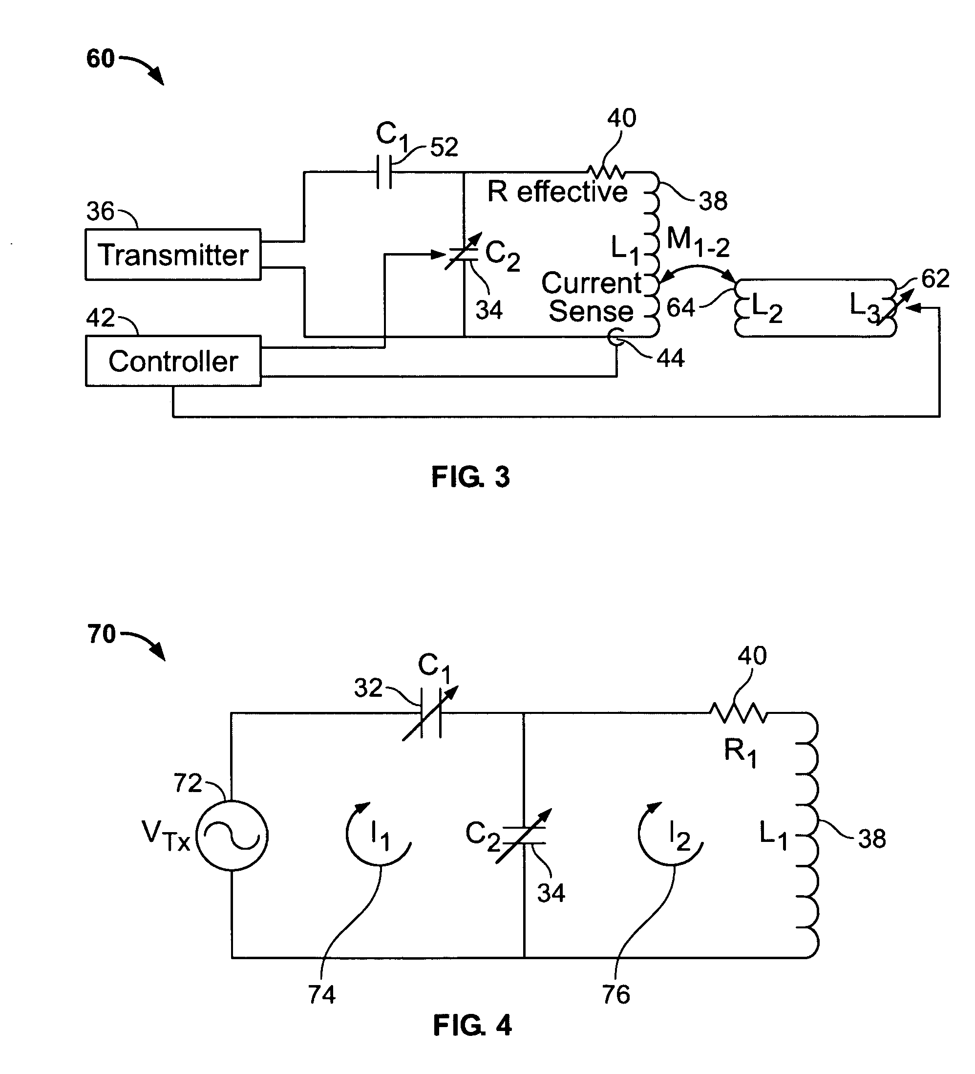
[0018]Various embodiments of the invention provide a system and method for resonant tuning with dynamic impedance matching. One or more variable or adjustable reactive elements are provided in a resonant circuit. The variable or adjustable reactive elements allow adjustment of at least one of the resonant frequency and the effective resonant impedance of the resonant circuit. It should be noted that the resonant circuit tuning system and method may be used in connection with any type of electronic system, for example, in electronic systems wherein a c...


PUM


Abstract

A resonant circuit tuning system and a method for tuning are provided. The resonant circuit tuning system may include a resonant circuit having a first capacitive element in series between a transmitter and an antenna coil and a second capacitive element in parallel with the transmitter and the antenna coil. At least one of the first capacitive element and second capacitive element may be configured to be varied. The resonant circuit tuning system also may include a controller for controlling a variable value of at least one of the first and second capacitive elements.

Description

BACKGROUND OF THE INVENTION[0001]1. Field of the Invention[0002]This invention relates generally to electronic tuning systems, and more particularly to a resonant tuning system with dynamic impedance matching.[0003]2. Description of the Related Art[0004]Magnetic fields are used in many electronic systems for a variety of purposes such as Electronic Article Surveillance (EAS), Radio Frequency Identification (RFID), metal detectors, magnetic imaging systems, remote sensing, communications, etc. In these various electronic systems, a magnetic coil may be used as a transmitter to project a magnetic field into a desired sensing region. More particularly, for the transmitters, a highly efficient method for generating magnetic fields includes the use of a series resonant LCR circuit that presents a low impedance to the transmitter at the transmit frequency. To achieve high magnetic field levels from the antenna of the transmitter, it is desirable for the transmitter to deliver high current...

Claims


Application Information

Patent Timeline
Patent Type & Authority Applications(United States)
IPC IPC(8): G08B13/14H01Q9/00
CPCG08B13/2477G06K19/0723
Inventor HALL, STEWART E.HERRING, RICHARD
Owner SENSORMATIC ELECTRONICS CORP
Why Eureka
Try Eureka