Apparatus and Method for Obtaining Images of a Borehole

a technology for obtaining images and boreholes, applied in the field of apparatus and methods for obtaining images of the wall of boreholes, can solve the problems of complex compensating camera optics, inability to mount the camera radially, and the mechanism to rotate the whole camera can be complex, so as to reduce the amount of image distortion and facilitate processing and interpretation.

Active Publication Date: 2007-12-27
SCHLUMBERGER TECH CORP
View PDF6 Cites 11 Cited by
  • Summary
  • Abstract
  • Description
  • Claims
  • Application Information

AI Technical Summary

Benefits of technology

[0013]By arranging for movement of the mirror, a flat mirror can be used, reducing the amount of distortion of the image and making processing and interpretation easier.

Problems solved by technology

The use of hemispherical or conical images or fish-eye lenses suffers from the problems of distortion of images leading to the need to have complex compensating camera optics to obtain a useful image.
Furthermore, the limited space available in most boreholes means that it is often not possible to mount the camera radially.
Also, the mechanism to rotate the whole camera can be complex.

Method used


Image

  • Apparatus and Method for Obtaining Images of a Borehole
  • Apparatus and Method for Obtaining Images of a Borehole

Examples


Embodiment Construction

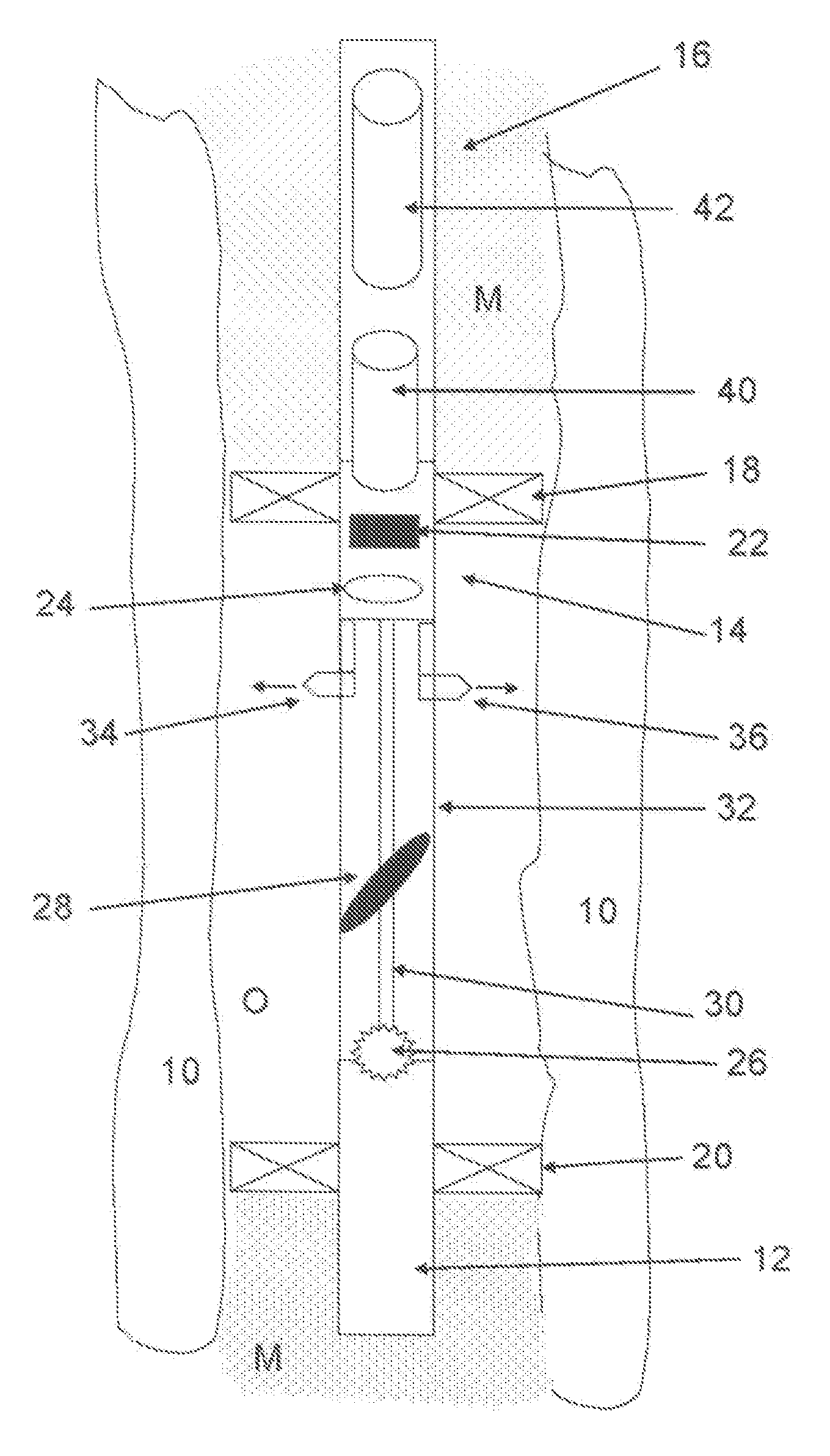
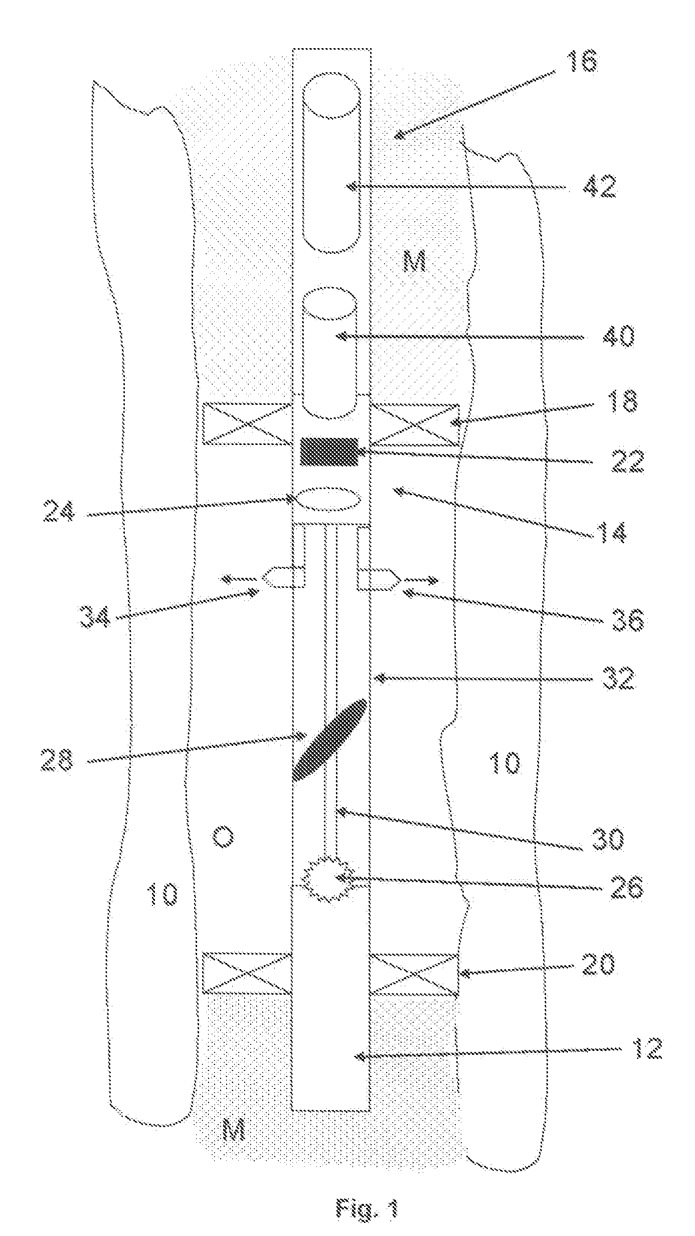
[0030]The apparatus shown in FIG. 1 comprises a wireline tool according to one embodiment of the invention for obtaining images in wells such as oil, water and gas wells drilled through underground formations 10. The tool comprises a tool body 12 that is suspended in the well by means of a wireline cable or coiled tubing (not shown). The tool body includes an imaging section 14 and a pumpout section 16.

[0031]The imaging section 16 comprises a pair of spaced inflatable packers 18, 20. A CCD camera 22 and lens 24 are located in an upper part of the imaging section near the packer 18. The camera 22 is maintained in a pressure-tight cartridge at atmospheric pressure and its temperature controlled by a suitable control system and / or insulation, and is aligned on the axis of the tool body 12 directed downwardly towards the opposite end of the tool body, at which a light source 26 is located near the packer 20. The lens 24 includes a focusing and zoom mechanism. Interposed between the ligh...


PUM


Abstract

Apparatus for obtaining images of the wall of a borehole, comprises a tool body; a light source mounted on the tool body and arranged to illuminate the borehole wall; a camera mounted in the tool body; and a mirror moveably mounted on the tool body and spaced axially from the camera and arranged to reflect an image of the borehole wall at the camera, wherein the movement of the mirror allows images of different parts of the borehole wall to be reflected at the camera.

Description

TECHNICAL FIELD [0001]This invention relates to apparatus and methods for obtaining images of the wall of a borehole. It is particularly applicable to obtaining images in oil, water or gas wells, or the like.BACKGROUND ART [0002]There are a number of existing techniques by which images of the inside of a borehole are obtained. However, most of these rely on reconstructing an image on the basis of measurements made of other than optical properties. Measurements used for such imaging include electrical conductivity or permittivity, acoustic impedance or slowness, or density of photoelectric effect. It is also desirable to obtain optical images to better understand the formation and the state of the borehole.[0003]Certain tools have been proposed for obtaining optical images in boreholes. Several have a camera pointed axially down the borehole and can image flowing fluids together with some neighbouring part of the borehole wall. Such tools are dependent on the well fluid being either ...

Claims


Application Information

Patent Timeline
Patent Type & Authority Applications(United States)
IPC IPC(8): H04N7/18H04N9/47E21B47/00
CPCE21B33/124E21B47/0002G02B23/2484G02B23/2453G02B23/02E21B47/002
Inventor VESSEREAU, PATRICKCHEUNG, PHILIPCODAZZI, DANIEL
Owner SCHLUMBERGER TECH CORP
Why Eureka
Try Eureka