Method and device for video encoding and decoding

a video and video encoding technology, applied in the field of digital video encoding and decoding, can solve the problems of unfavorable network performance, large data volume, and inability to fully support video streams, and achieve the effects of improving robustness against data loss, reducing error propagation, and improving network traffic smoothness

Inactive Publication Date: 2007-12-27
NTNU TECH TRANSFER
View PDF5 Cites 7 Cited by
  • Summary
  • Abstract
  • Description
  • Claims
  • Application Information

AI Technical Summary

Benefits of technology

[0018] Methods and devices in accordance with the principles of the present invention may lead to improved smoothness of the network traffic.
[0019] Methods and devices in accordance with the principles of the present invention may involve reduced error propagation and improved robustness against data loss, while still maintaining improved smoothness of the network traffic.

Problems solved by technology

Digital video signals, in non-compressed form, typically contain very large amounts of data.
The use of motion compensation, such as specified in the above specifications, may have an unfavourable effect on network performance when a coded video signal is transmitted through a digital telecommunication network, in particular a network with variable bit rate transmission such as an IP network.
Since the 1-type pictures need significantly more bits for transmission than a P-type or B-type picture, the resulting video stream may become bursty.
This may, in turn, lead to poor multiplexing properties, buffer overflow, and large network delays.
A disadvantage of the intra slice coding approaches suggested in the prior art is that errors due to an accidental data loss may propagate through numerous frames in the encoded video data.
Such error propagation may result in poor robustness.

Method used


Image

  • Method and device for video encoding and decoding
  • Method and device for video encoding and decoding
  • Method and device for video encoding and decoding

Examples


Embodiment Construction

[0025] Reference will now be made in detail to the present invention, examples of which are illustrated in the accompanying drawings. Wherever possible, the same reference numbers will be used throughout the drawings to refer to the same or like parts.

[0026] In the following description, the expression “predictive-coded data” should for simplicity be interpreted as both regular predictive-coded data, which are coded using motion compensated prediction from previous pictures, and bidirectional predictive data, i.e. data coded using motion compensated prediction from both previous and future pictures.

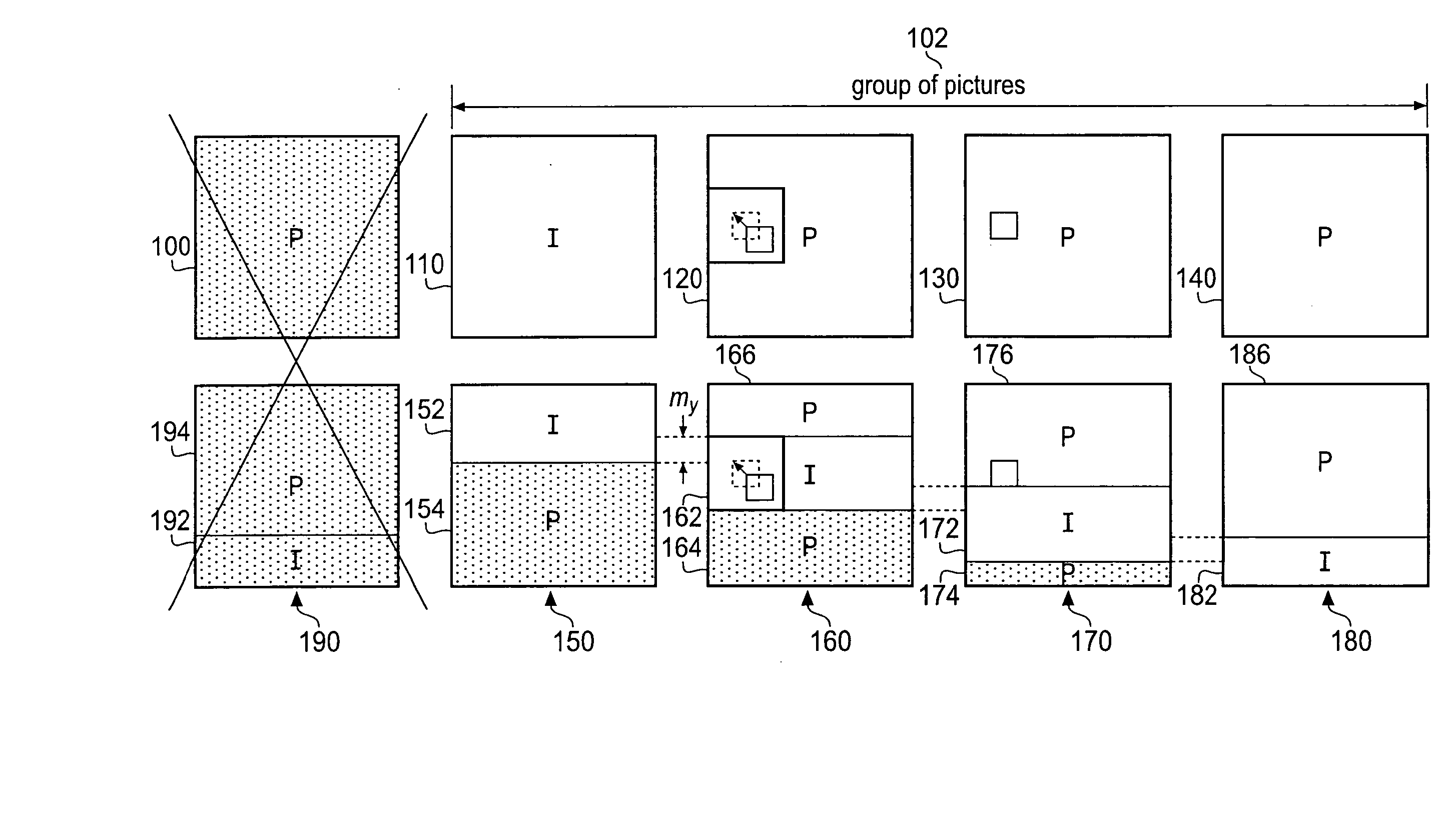
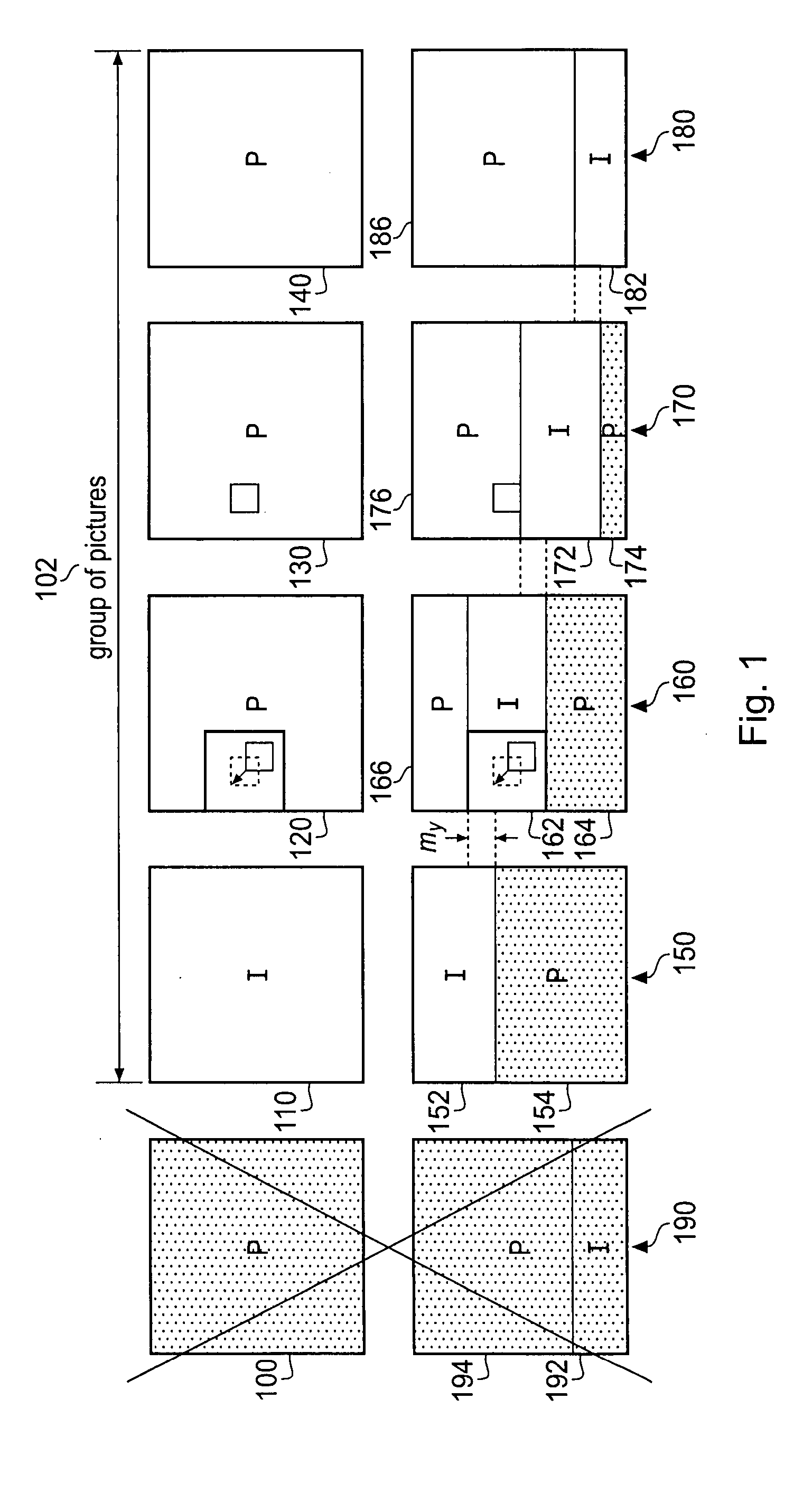
[0027]FIG. 1 is a schematic block diagram illustrating principles of the invention.

[0028] The upper row of squares 100, 110, 120, 130, 140 are intended to represent the principles of prior art video coding, such as video coding in accordance with the H.262 specification. In the upper row, 100 denotes frame number n, 110 denotes frame number n+1, 120 denotes frame number n+2, 130 denote...


PUM


Abstract

The present invention relates to a method and device for providing encoded video data from a video signal. The method comprises the steps of providing intra-coded picture data and predictive-coded picture data, based on the video signal, and generating a first and a second frame of said encoded video data. In the generating step of the intra-coded picture data is arranged in first and second slices in the first and second frames, respectively. The slices are arranged in an overlapping manner in the frames, advantageously with a vertical overlap my which is equal to or greater than a maximum absolute length of a vertical motion vector. The invention also relates to a corresponding decoding method and device, as well as a corresponding video encoder, a video decoder and a video codec. The invention may be implemented and used in accordance with standard specifications such as H.264. The invention leads to increased network smoothness as well as improved robustness and reduced error propagation during transmission.

Description

FIELD OF THE INVENTION [0001] The present invention relates in general to the technical field of digital video encoding and decoding. [0002] More specifically, the invention relates to a method, a device and a video encoder for providing encoded video data from a video signal, and a method, a device and a video decoder for providing a decoded video signal from encoded video data. The invention also relates to a method for video encoding and decoding, as well as a video codec. BACKGROUND OF THE INVENTION [0003] Digital video signals, in non-compressed form, typically contain very large amounts of data. Due to high temporal and spatial correlations and redundancy, such data may be considerably reduced or compressed by means of video coding. Video coding and decoding processes are thus commonly used to reduce the amount of data which is actually required for certain applications, such as storing the video signals or transmitting signals through a digital communication network. [0004] S...

Claims


Application Information

Patent Timeline
Patent Type & Authority Applications(United States)
IPC IPC(8): H04B1/66
CPCH04N19/52H04N19/583H04N19/593H04N19/61
Inventor FIDLER, MARKUSEMSTAD, PEDER J.PERKIS, ANDREW
Owner NTNU TECH TRANSFER
Why Eureka
Try Eureka