Optical wireless communication device

a wireless communication and optical technology, applied in the field of optical wireless communication devices, can solve the problems of increasing power consumption, difficult to satisfy these contradictory requirements, and reducing the power consumption of the device only slightly, so as to achieve the effect of efficient power us

Active Publication Date: 2007-12-27
MICROSOFT TECH LICENSING LLC
View PDF2 Cites 11 Cited by
  • Summary
  • Abstract
  • Description
  • Claims
  • Application Information

AI Technical Summary

Benefits of technology

[0036]In the present invention, the control unit can supply the charge power to the television receiver during the charge mode to assist the operation of the television receiver.
[0037]According to the configuration as described above, the electronic equipment including the optical wireless communication devic...

Problems solved by technology

Although there exists a strong demand for higher communication speed and extended communication distance, satisfying these two requirements requires more power consumption.
In other words, increasing communication speed and communication distance is contradictory to providing lower power consumption, and therefore it is difficult to satisfy these contradictory requirements.
However, even if shutdown mode is ex...

Method used


Image

  • Optical wireless communication device
  • Optical wireless communication device
  • Optical wireless communication device

Examples


Embodiment Construction

[0041]Hereinafter, an embodiment of the present invention will be described in detail with reference to the accompanying drawings.

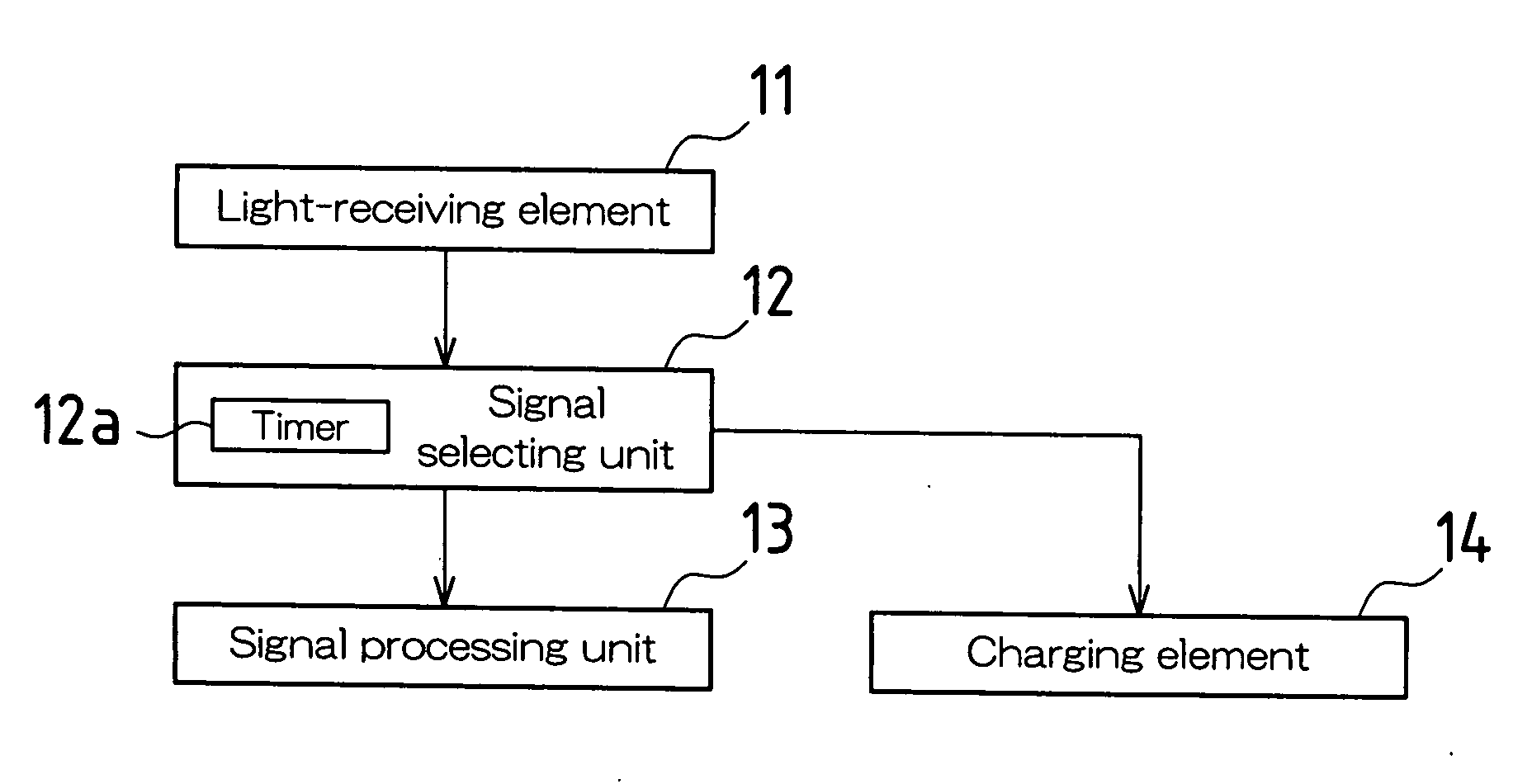
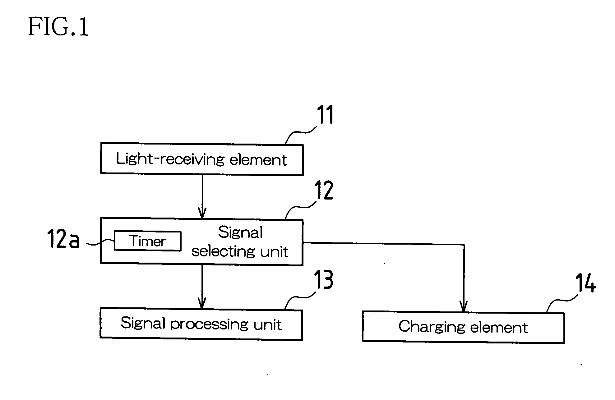
[0042]FIG. 1 is a block diagram schematically showing an optical wireless communication device according to an embodiment of the present invention. The optical wireless communication device of this embodiment is mounted in, for example, a cell phone and is used to communicate small-volume text data (e.g., telephone numbers, e-mail addresses) with other piece(s) of equipment.

[0043]This optical wireless communication device includes a light-receiving element 11, a signal selecting unit 12, a signal processing unit 13 and a charging element 14. The light-receiving element 11 receives an optical communication signal emitted from other piece(s) of equipment. The signal selecting unit 12 receives a received light output of the light-receiving element 11 and outputs the received light output to either the signal processing unit 13 or the charging element 14. The...


PUM


Abstract

An optical wireless communication device mounted in electronic equipment includes: a light-receiving element for receiving an optical communication signal; and a control unit that monitors a received light output of the light-receiving element. When the control unit determines that the received light output represents the optical communication signal, it selects and executes communication mode for the optical communication signal. When the control unit determines that the received light output does not represent the optical communication signal, it selects and executes charge mode in which the received light output is used as a charge power.

Description

BACKGROUND OF THE INVENTION[0001]This application claims priority under 35 U.S.C. § 119(a) on Patent Application No. 2006-163602 filed in Japan on Jun. 13, 2006, the entire contents of which are hereby incorporated herein.[0002]The present invention relates to an optical wireless communication device mounted in electronic equipment.[0003]As widely known, IrDA 1.0 and IrDA 1.1, standards for optical wireless communication devices that allow wireless communication between different pieces of equipment using light, were established in 1994. These standards do not require the formation of networks and readily allow peer-to-peer (one to one) communication. Currently, they are implemented mainly in cell phones, and are expected to be implemented in printers and television receivers in the future.[0004]Optical wireless communication devices as described above, which are mounted in, for example, cell phones, function mainly to communicate small-volume text data such as telephone numbers and...

Claims


Application Information

Patent Timeline
IPC IPC(8): G02B6/28H04B10/11H04B10/07H04B10/114H04B10/524H04B10/80
CPCH04B10/807
Inventor WATANABE, NOBUHISA
Owner MICROSOFT TECH LICENSING LLC
Why Eureka
Try Eureka