System and method for receiving coherent, polarizaztion-multiplexed optical signals

a polarization multiplexing and optical signal technology, applied in electromagnetic transmission, electrical equipment, transmission, etc., can solve the problems of polarization diversity receivers that employ two optical hybrids, experience arbitrary polarization transformation, and high cost of optical hybrids

Active Publication Date: 2007-12-27
ALCATEL-LUCENT USA INC
View PDF45 Cites 57 Cited by
  • Summary
  • Abstract
  • Description
  • Claims
  • Application Information

AI Technical Summary

Problems solved by technology

Unfortunately, by the time the received optical signal has reached the receiver, it has experienced arbitrary polarization transformation as a result of being transmitted over a fiber.
Unfortunately, an optical hybrid is a

Method used


Image

  • System and method for receiving coherent, polarizaztion-multiplexed optical signals
  • System and method for receiving coherent, polarizaztion-multiplexed optical signals
  • System and method for receiving coherent, polarizaztion-multiplexed optical signals

Examples


Embodiment Construction

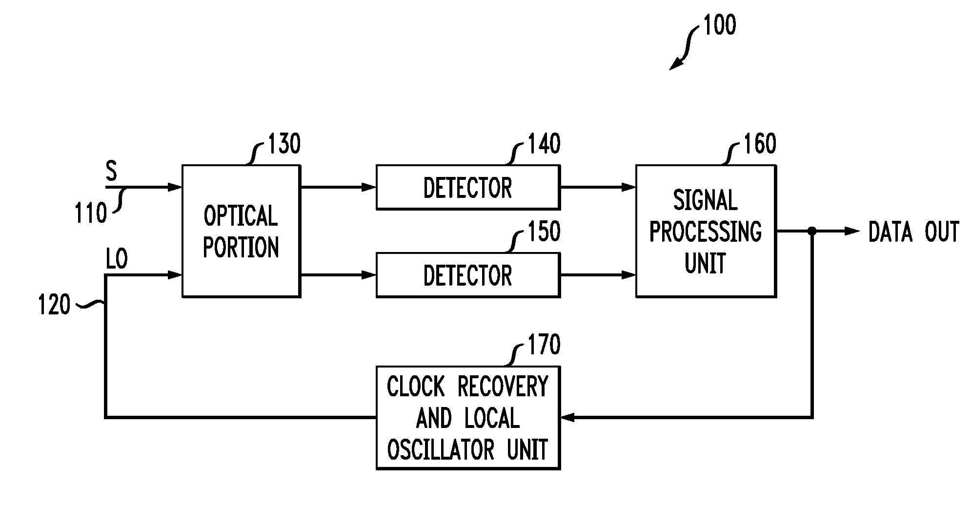
[0015]Referring initially to FIG. 1, illustrated is a block diagram of a polarization diversity receiver generally designated 100 and configured to demodulate and convert a received optical signal S 110 that is coherent and polarization-multiplexed into electrical signals representing in-phase and quadrature components of S 110. Unlike conventional polarization diversity receivers, the receiver 100 needs only one optical hybrid.

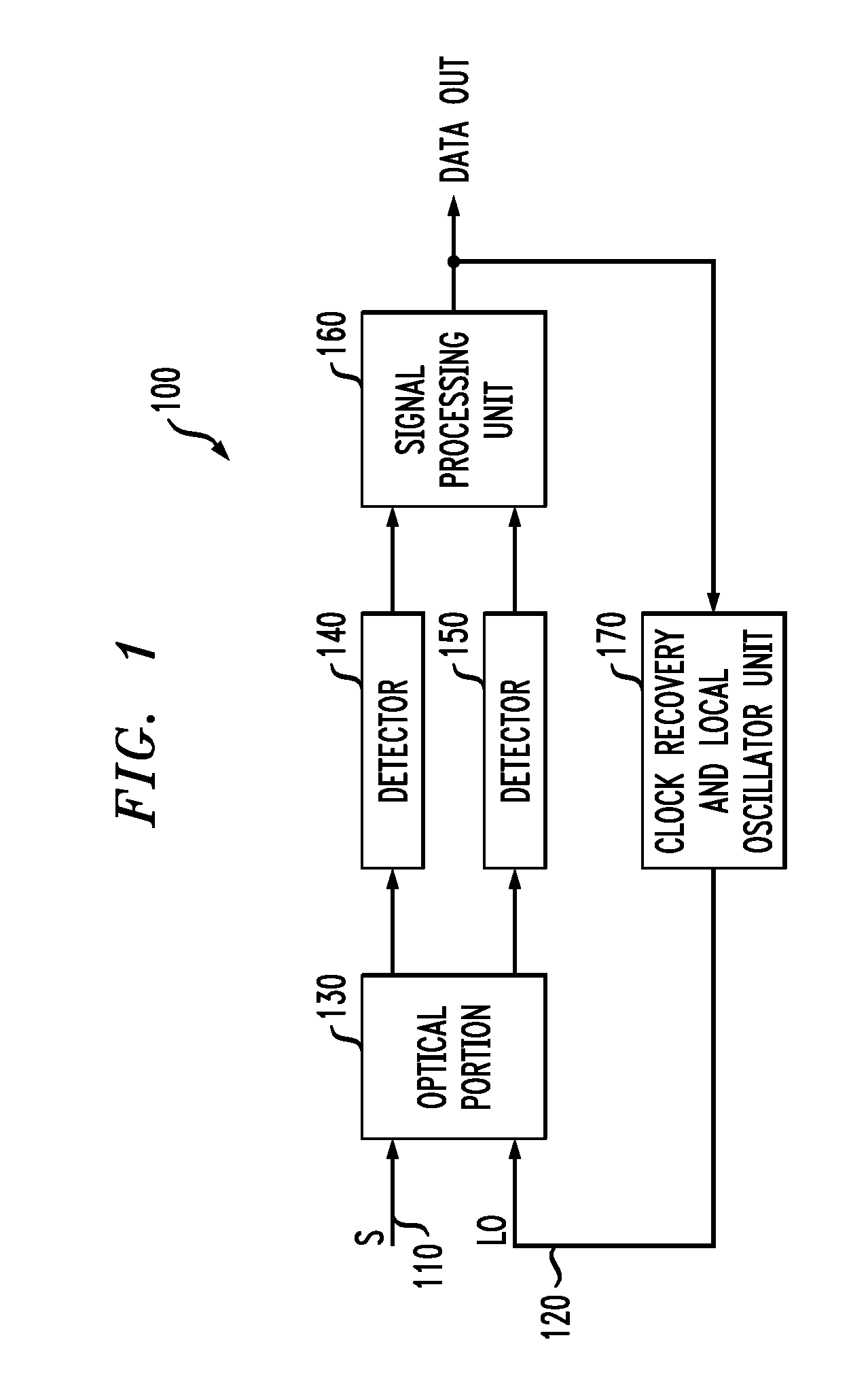
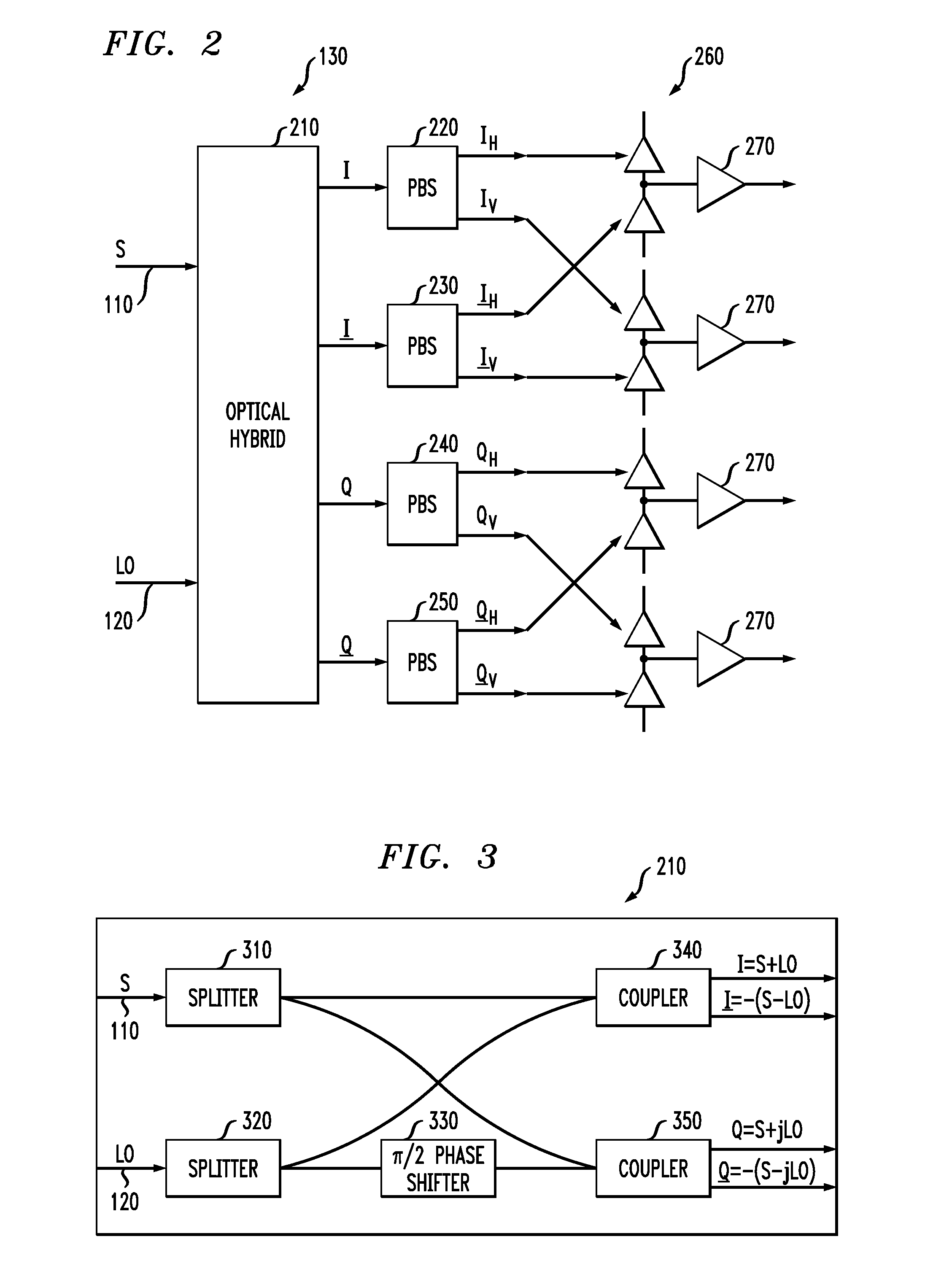
[0016]The receiver 100 receives and demodulates S 110 using a coherent, local oscillator optical signal LO 120. S 110 and LO 120 are received into an optical portion 130, which may include a polarization-insensitive optical hybrid. The optical portion 130 splits and couples S 110 and LO 120 in a manner that will be shown in FIG. 3 to yield at least two output optical signals that are respectively provided to detectors 140, 150, which are photodetectors, such as photodiodes. In turn, the detectors 140, 150 provide electrical signals to a signal processing unit...


PUM


Abstract

An apparatus, a polarization diversity receiver and a method of receiving a received optical signal. In one embodiment, the apparatus includes: (1) an optical device configured to separate in-phase and quadrature components of a received optical signal, to transmit the in-phase components to a first optical output thereof and to transmit the quadrature components to a second optical output thereof, (2) a first polarization splitter coupled to receive light at the first optical output and (3) a second polarization splitter coupled to receive light at the second optical output.

Description

TECHNICAL FIELD OF THE INVENTION[0001]The invention is directed, in general, to optical coherent communication systems and, more particularly, to a system and method for receiving coherent, polarization-multiplexed optical signals.BACKGROUND OF THE INVENTION[0002]Optical coherent communication systems widely researched due to their potential ability to communicate vast amounts of information quickly. In optical coherent communication systems, a so-called “optical hybrid” is used to overlay a received optical signal and a local oscillator optical signal, resulting in a demodulation of the received optical signal and yielding in-phase components I and I and quadrature components Q and Q. These components I, I, Q and Q, are then transformed into electrical signals using photodetectors. This configuration is sometimes called a “phase diversity receiver.” Electronic logic circuitry can then be used to compare the electrical signals to one another, one or more thresholds, or both, to yiel...

Claims


Application Information

Patent Timeline
IPC IPC(8): H04B10/00
CPCH04B10/61H04B10/63H04B10/614H04B10/613H04B10/67
Inventor KANEDA, NORIAKILEVEN, ANDREAS B.
Owner ALCATEL-LUCENT USA INC
Why Eureka
Try Eureka