Distributor of a gas-liquid two phase fluid

a technology of two-phase fluid and distribution channel, which is applied in the direction of fluid circulation arrangement, refrigeration machines, lighting and heating equipment, etc., can solve the problem of extremely small energy loss (pressure loss)

Inactive Publication Date: 2008-01-03
DENSO CORP
View PDF4 Cites 30 Cited by
  • Summary
  • Abstract
  • Description
  • Claims
  • Application Information

AI Technical Summary

Benefits of technology

[0009]An object of the present invention is to provide a distributor that can evenly supply two-phase refrigerant flowing in by various flow states to the pipes without pressure loss.

Problems solved by technology

Further, the two-phase fluid moves inside the vessel by gravity, so the energy loss (pressure loss) is extremely small.

Method used


Image

  • Distributor of a gas-liquid two phase fluid
  • Distributor of a gas-liquid two phase fluid
  • Distributor of a gas-liquid two phase fluid

Examples


first embodiment

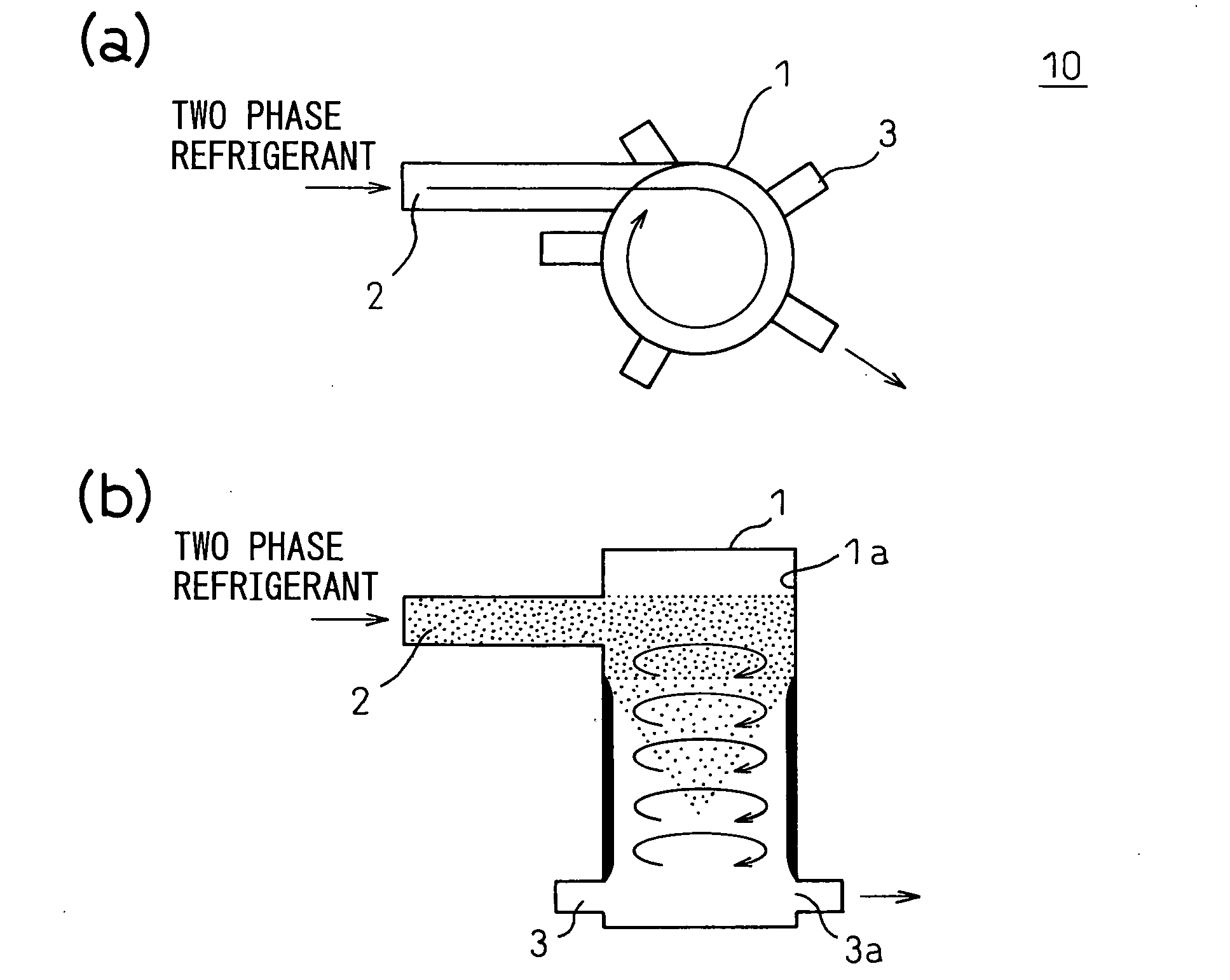
[0024]FIG. 1 shows a first embodiment of a distributor according to the present invention by schematic views. FIG. 1(a) shows a top view of the distributor, while FIG. 1(b) shows a side cross-sectional view of the distributor. In FIG. 1, reference numeral 10 is a distributor of the first embodiment, 1 is a cylindrical vessel, 2 is an inlet pipe, and 3 are distribution pipes.

[0025]The inlet pipe 2 is connected in a tangential direction with respect to the circular cross-section of the upper portion of the cylindrical vessel 1. At the lower portion of the cylindrical vessel 1, a plurality of distribution pipes 3 are connected at positions separated by equal angles in the peripheral direction and extend outward radially. That is, the plurality of distribution pipes 3 are connected to the cylindrical vessel 1 so that the intervals between them become equal distances.

[0026]Further, the gas phase two-phase refrigerant (for example, having a ratio of the liquid phase to the gas phase of ap...

second embodiment

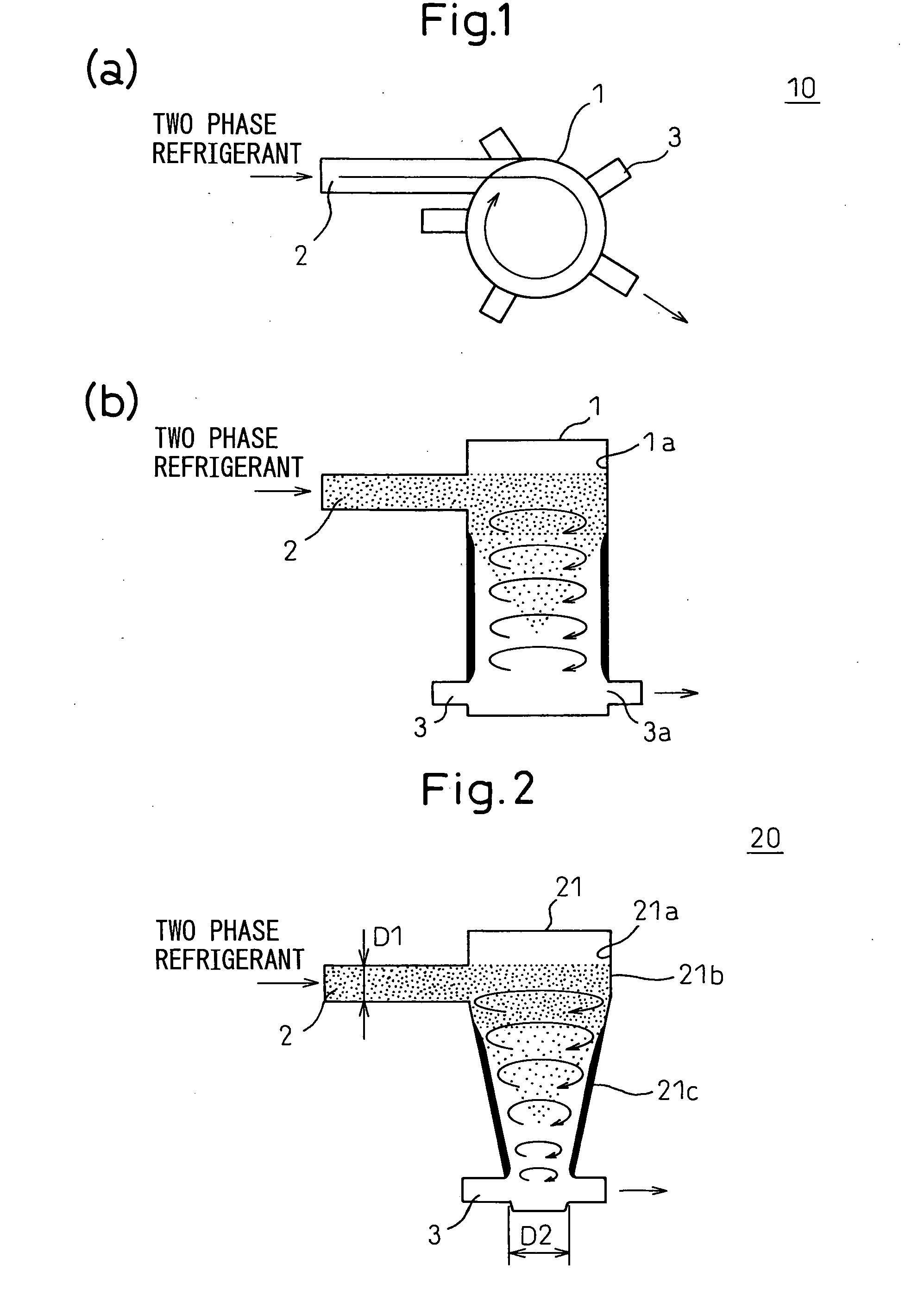
[0029]FIG. 2 shows the side cross-section of a second embodiment of the distributor according to the present invention by a schematic view. The top view is the same as FIG. 1 (a), so is omitted. The distributor of the second embodiment differs from the first embodiment in only the cylindrical vessel. Therefore, parts substantively the same as the parts of the first embodiment are assigned the same reference notations and explanations are omitted.

[0030]In FIG. 2, reference numeral 20 is the distributor of the second embodiment, while 21 is a vessel with a cylindrical upper portion 21b and an inverted conical lower portion 21c (below referred to as “the upper portion cylindrical vessel”).

[0031]The two-phase refrigerant forms a swirl flow along the inner surface 21a of the vessel 21 and flows toward the bottom of the vessel 21. At that time, the liquid film on the reverse conical surface generated by the centrifugal separation action is subjected to an upward force component by the rev...

third embodiment

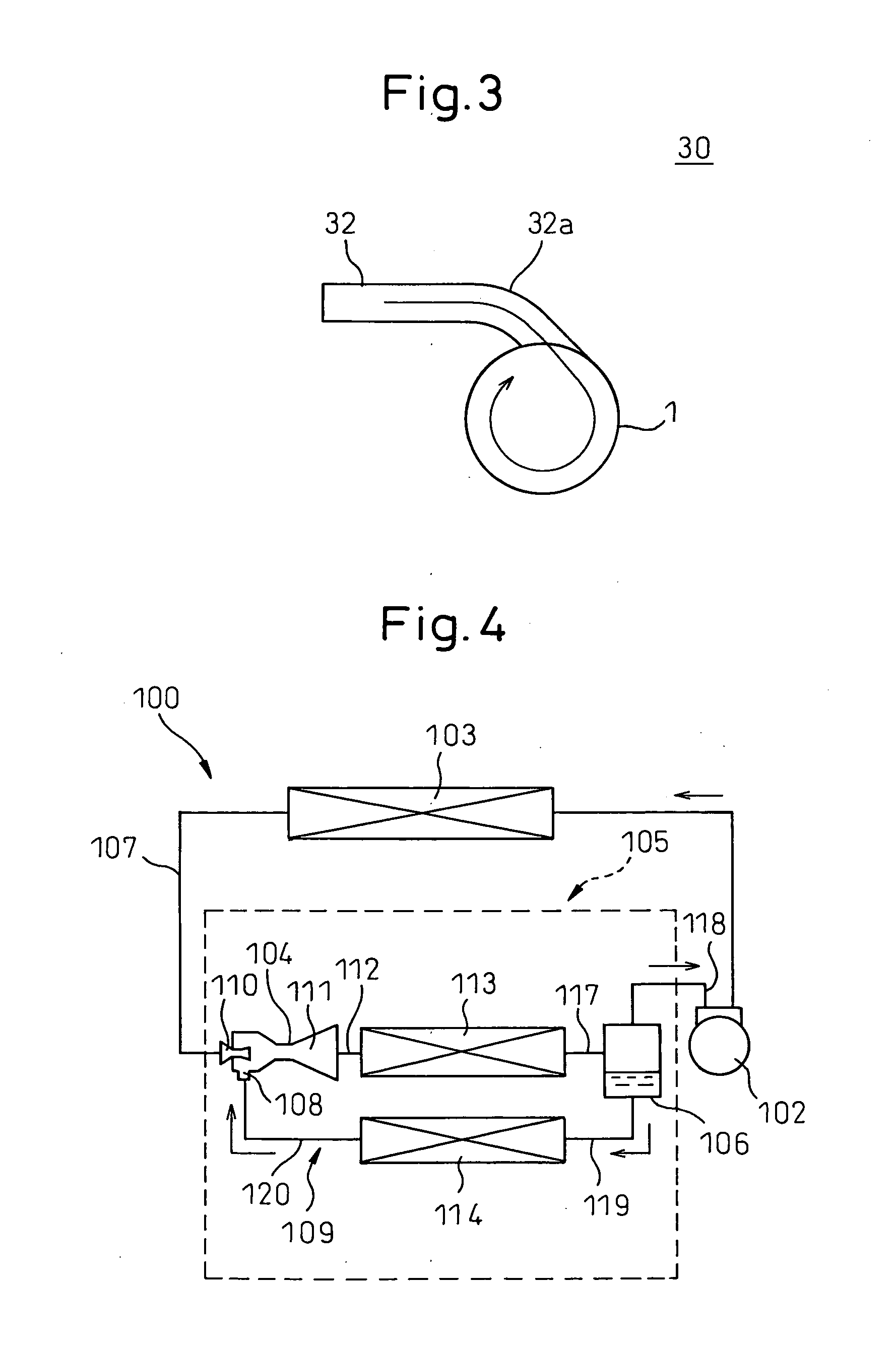
[0034]FIG. 3 shows a top view of a third embodiment of a distributor according to the present invention by schematic view. The side cross-sectional view is the same as FIG. 1(b), so is omitted. The distributor of the third embodiment differs from the first embodiment in only the inlet pipe is different. Therefore, parts substantively the same as the parts of the first embodiment are assigned the same reference notations and explanations are omitted.

[0035]In FIG. 2, reference numeral 30 is the distributor of the third embodiment, while 32 is the inlet pipe. The inlet pipe 32 has a curved portion 32a that curves just before being connected to the cylindrical vessel 1. This curve portion 32a has the function of generating a centrifugal separation action, so it becomes possible to make cylindrical vessel 1 smaller by that amount.


PUM


Abstract

A distributor able to evenly supply influent two-phase refrigerant flowing in by various flow states to different pipes with an extremely small pressure loss, that is, a distributor of a gas-liquid two-phase fluid distributing a gas-liquid two-phase fluid flowing in from an inlet pipe into a plurality of distribution pipes, provided with a cylindrical vessel with a cylindrical upper part, an inlet pipe connected in a tangential direction with respect to a circular cross section of the upper portion of the cylindrical vessel, and distribution pipes connected to a lower portion of the cylindrical vessel.

Description

BACKGROUND OF THE INVENTION[0001]1. Field of the Invention[0002]The present invention relates to a distributor provided in a refrigerant circuit of an air conditioning system or the like and distributing a two-phase refrigerant to a plurality of heat exchangers and the like, more particularly relates to structure uniformly dividing a two-phase refrigerant of a uniform mixing ratio.[0003]2. Description of the Related Art[0004]In the past, as shown in FIG. 4, there has been proposed a refrigeration cycle 100 connecting a refrigerant compressor 102, refrigerant condenser 103, ejector 104, first refrigerant evaporator 113 of an indoor heat exchanger 105, and a gas-liquid separator 106 successively in a ring by refrigerant piping 107 and connecting a liquid phase refrigerant side of the gas-liquid separator 106 and a suction part 108 of the ejector 104 by bypass piping 109 provided with a second refrigerant evaporator 114 of the indoor heat exchanger 105 (Japanese Patent No. 3265649).[00...

Claims


Application Information

Patent Timeline
Patent Type & Authority Applications(United States)
IPC IPC(8): F25B39/02
CPCF25B2400/02F25B39/028F25B2341/0012F25B2400/23F25B41/45
Inventor OOMURA, GENTAROUNISHIJIMA, HARUYUKIYAMADA, ETSUHISATAKEUCHI, HIROTSUGUMATSUI, HIDEYAFUJIWARA, RYOKO
Owner DENSO CORP
Why Eureka
Try Eureka