[0006]The object of the invention is to provide an electric heating device that complies with the above requirements, offers adequate safety and avoids the abovementioned problems,
[0008]The electric heating device according to the invention offers the
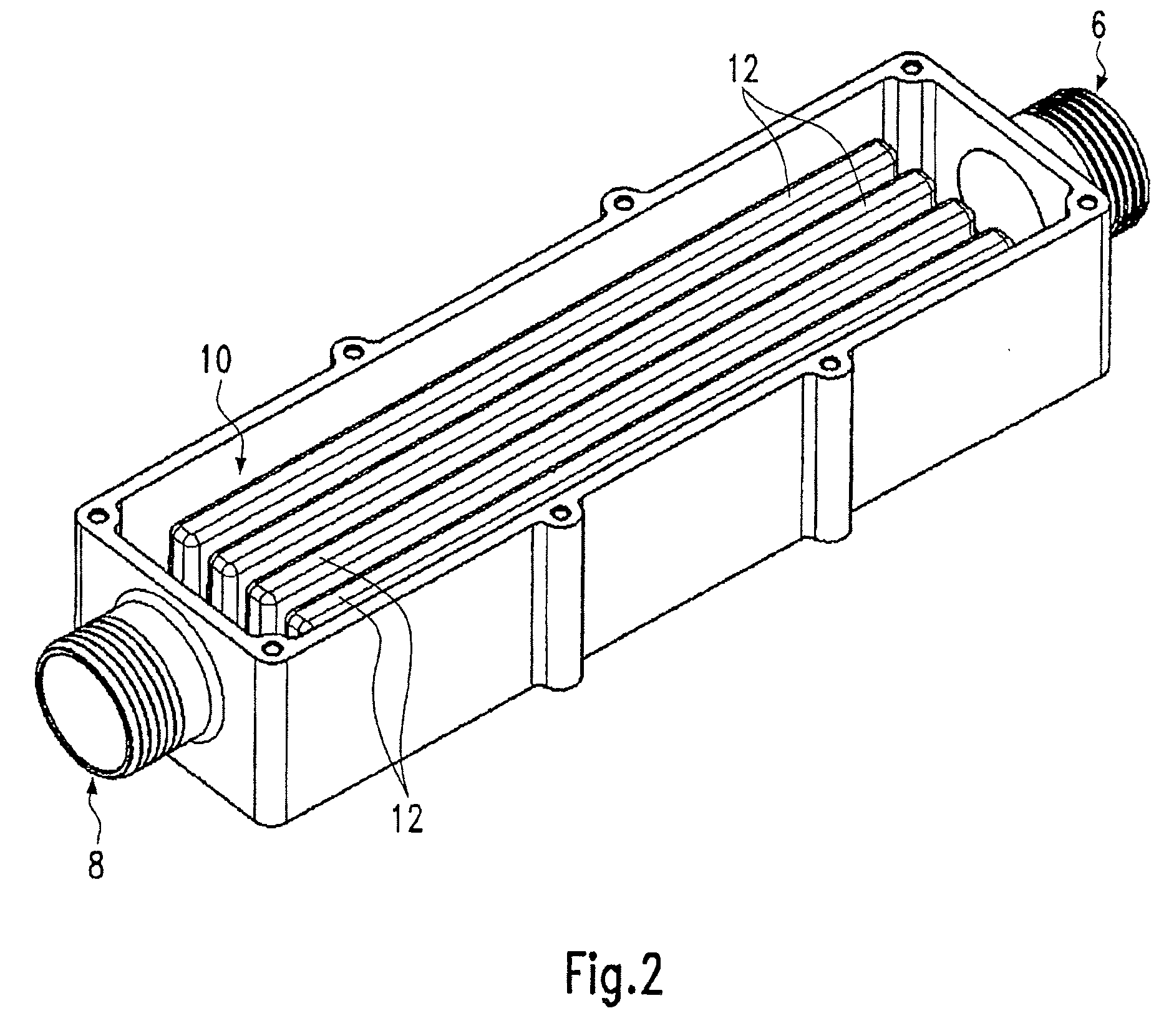
advantage that, due to the separating wall, the heat-dissipating medium, for example, water or oil, is reliably separated from the electric heating element. Accordingly, any heat-dissipating medium can be used, including such media as could, in the event of direct contact with the electric heating element, possibly damage this electric heating element and / or cause a
short circuit.
[0013]The pressure element is likewise formed from a good heat-conducting material and preferably lies with its full surface against the heating element, optionally with the electrically insulating plate as an intermediate layer. In this way, good heat conduction to both sides of the electric heating element is guaranteed by the opposing side pieces of the U-shaped recess for transfer to the medium in the circulation chamber. To this end, the pressure element is pressed with a large force into the U-shaped recess, in order to brace the electric heating element in the recess, namely by introducing the pressure element along the length of plate-shaped electric heating elements. The later pressure surfaces of the electric heating element should be level and smooth for this. If the pressing forces are large, it is preferable that the pressure element be slid in against an electrically insulating plate formed by a
ceramic plate, whereby the upper surface of this electrically insulating plate opposes the sliding-in motion of the pressure element with a lower
frictional resistance. Practical attempts have shown that the
insertion force for bringing the pressure element to a heating element amounts to several hundred Newton. Not least due to this reason, it is preferred to arrange a number of electric heating elements along the length of the recess, one behind the other, each one of which is braced in the recess by separate pressure elements. The pressure element preferably has a
footprint that corresponds to the
footprint of the electric heating element, so that heat generated by the heating element can be conducted transversely into the side pieces without disturbance.
[0014]Between the electrically insulating plates and the at least one PTC heating element arranged between them, preferably
electric contact plates are arranged on each side of the PTC heating element and electrically contacted to the PTC heating elements. The contact plates preferably have extension sections formed on the contact plates as a single piece, whereby these extension sections project beyond the electrically insulating plates on diagonally opposing sides of the heating element. As one result of the diagonally offset arrangement of the extension sections it is prevented that these sections are opposed, spaced apart by the thickness of the PTC heating elements only, so that the risk of a short-circuit forming is further reduced and, furthermore, the
electrical connection of the extension sections to a power supply is simplified, even while taking into consideration sufficient protection against short-circuit. The size of the surface area of the contact plates arranged between the insulating plates essentially corresponds to the outer surface of the at least one PTC heating element, whereby this outer surface faces the interior side of the insulating plate, with a view to the best possible electrical contacting of the PTC heating elements. Accordingly, each of the PTC heating elements is in contact with the contact plates across the entire surface. In contrast, the insulating plates also form a slightly projecting edge, also with a view to sufficient spacing of the heating elements from the housing along the circumference of the heating elements. The electric heating element can have one or more PTC heating elements. The use of a number of PTC heating elements is preferred particularly when the
voltage is more than 230 V, in order to be able to operate these PTC heating elements as parallel resistors. Through this, the resistance realised with the individual PTC heating elements does not have to be unnecessarily reduced, which can lead to a reduced
breakdown voltage. When the
voltage is <230 V, a single PTC heating element is preferably realized in an electric heating element.
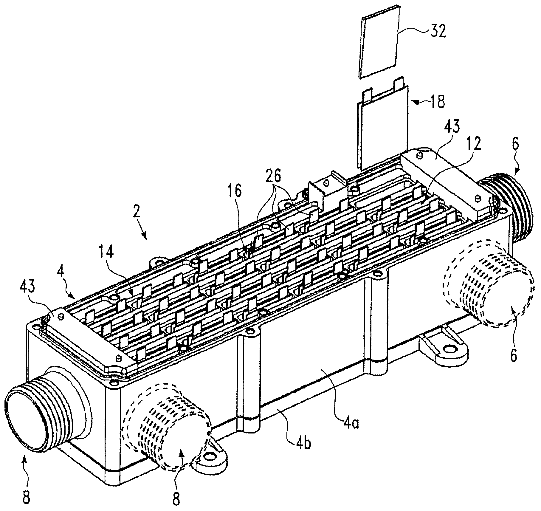
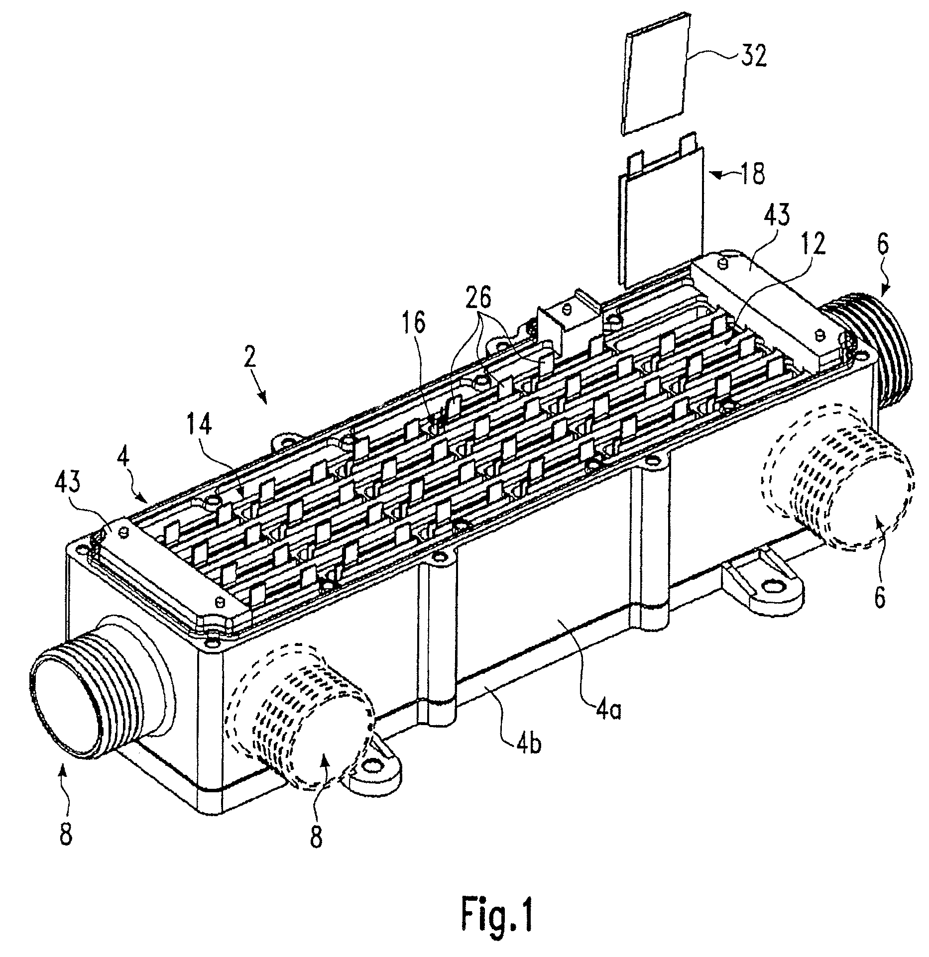
[0016]Particularly when the heating device is used in the engine compartment of a motor vehicle, and for sealing the heating chamber, according to a preferred further development of the invention under consideration it is proposed to provide a cover that has a power and
signal terminal and that seals the heating chamber. This cover furthermore has contact elements that act in combination with the plug-in elements on the upper side of the
printed circuit board. The contact elements preferably can be slid into one another, forming a contact, when the cover is placed into position, and preferably extend parallel to the extension sections, so that the movement for placing the cover into position along the length of the extension sections not only leads to the contacting of the contact elements that lead to the power and
signal terminal, but also to good retention of the extension sections at the opposite side of the
printed circuit board.

