Tape cartridge

a cartridge and tape technology, applied in the field of tape cartridges, can solve problems such as radial deformation of tape mt, and achieve the effect of preventing a deformation of wound up tap

Active Publication Date: 2008-01-03
FUJIFILM CORP
View PDF4 Cites 3 Cited by
  • Summary
  • Abstract
  • Description
  • Claims
  • Application Information

AI Technical Summary

Benefits of technology

[0010]The present invention seeks to provide a tape cartridge capable of recording and reproducing record of a high accuracy servo signal, by preventin...

Problems solved by technology

This radial deformation of the tape MT has been a cause of some error such as recording miss which appears in magnetic record reproduction, because ...

Method used


Image

  • Tape cartridge
  • Tape cartridge
  • Tape cartridge

Examples


first embodiment

[0035]A configuration of a tape cartridge 1 according to the present invention will be described, firstly.

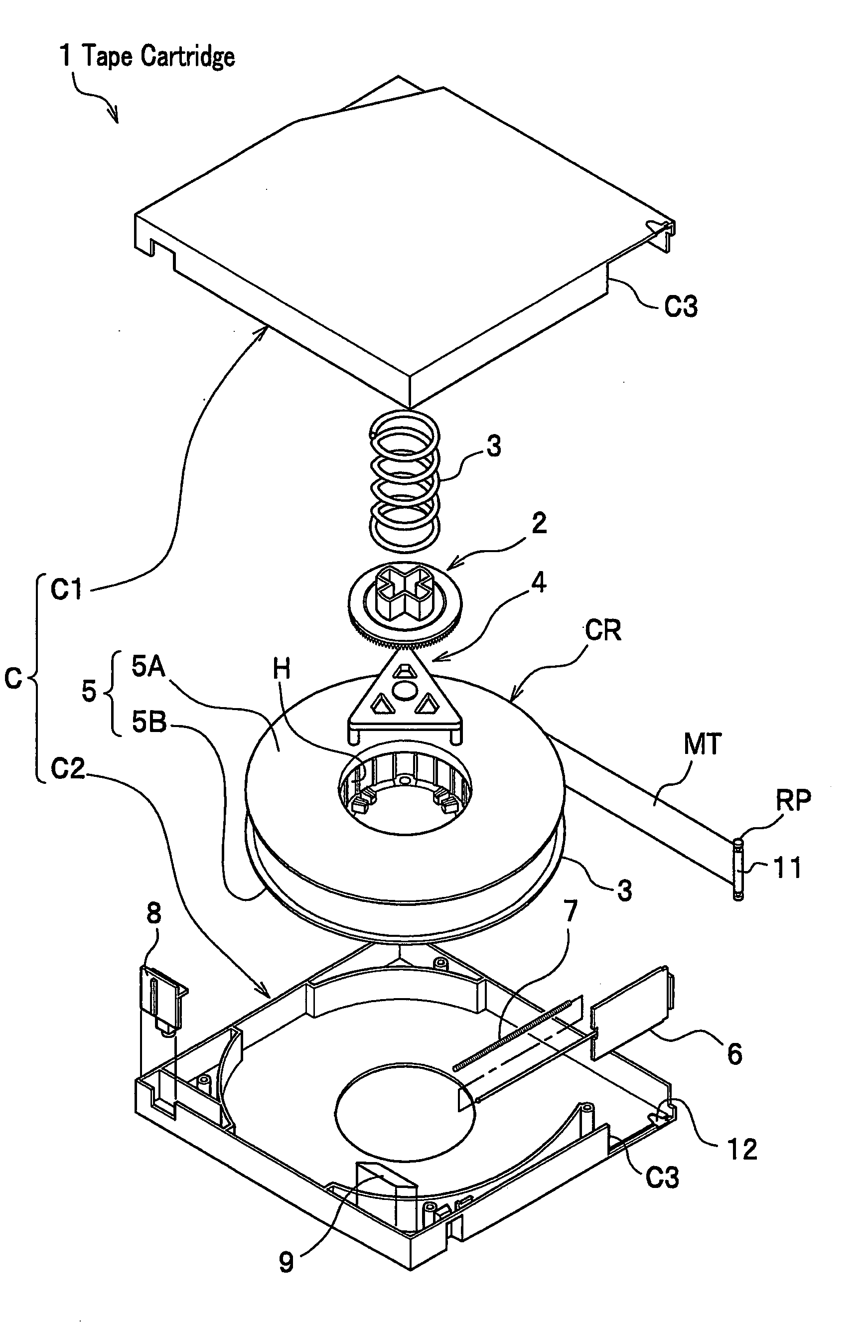
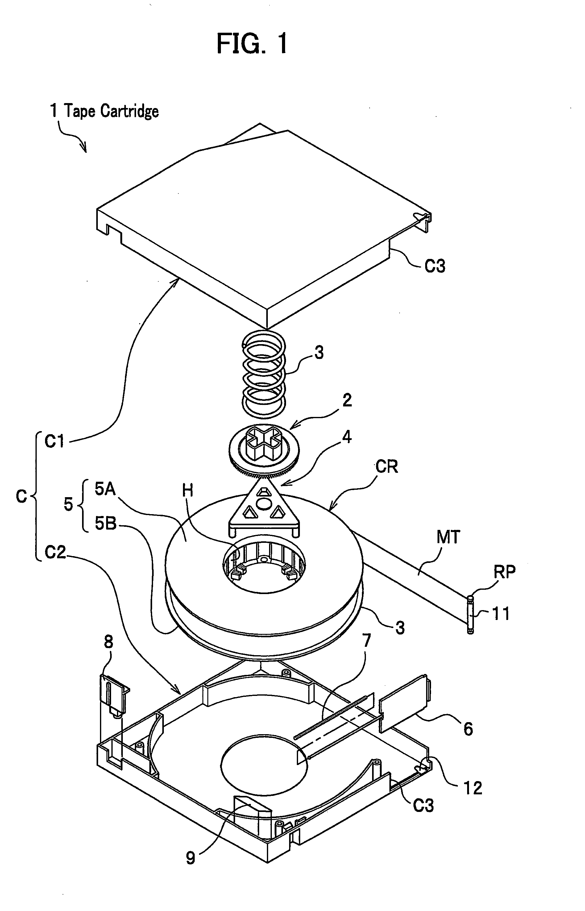
[0036]The tape cartridge 1 of FIG. 1 conforms to the so-called LTO (Linear Tape-Open) standard and includes, in a cartridge case C divided to an upper half C1 and a lower half C2, a single reel CR; a lock plate 2 and a compressive coil spring 3 for locking a rotation of the reel CR; a release pad 4 for releasing a lock of the reel CR; a hub H around which a tape MT is wound; a flange 5 including an upper flange 5A and a lower flange 5B welded to the hub H; a slide door 6 which opens and closes a tape-pull-out opening C3 provided across the lower half C2 and the upper half C1 in the cartridge case C; a torsion coil spring 7 which pushes the slide door 6 to a closing position of a tape-pull-out opening C3; a safety lug 8 for preventing erroneous erasure; a cartridge memory chip 9; a reel pin RP; and a clip 11. FIG. 1 illustrates a state where the tape MT is wound in the reel CR.

[0...

second embodiment

[0077]Next, a description will be made on a tape cartridge 1′ according to a second embodiment of the present invention.

[0078]Since, in the tape cartridge 1′ according to the second embodiment, the shape of the front end portion MT1 of the tape MT according to the first embodiment is changed only, the same symbols are used in the same configuration as those in the tape cartridge 1 according to the first embodiment, and a duplicated description will be omitted.

[0079]FIG. 6A is a plane view and a partial enlarged view of a part of the main part of the transport unit 22 of the front end portion MT1′ of the tape MT which retains the tape to be sucked and wound around in the tape cartridge according to the second embodiment.

[0080]FIG. 6B is a plane view and an enlarged view of a front end portion MT1′ of the tape MT having arc shaped chamfered portions to be sucked and wound around in the tape cartridge according to the second embodiment.

[0081]As illustrated in FIG. 6, in the tape MT of ...


PUM


Abstract

A tape cartridge including a tape capable of recording and reproducing a high accuracy servo signal, by preventing a deformation of the tape by preventing turning up of a front end portion of a tape when the front end portion is adhered to a reel hub. The tape cartridge includes the tape, a single reel having a reel hub around which the tape is wound and a cartridge case in which the reel is installed, and the front end portion of the tape is adhered to the reel hub, and each corner of the front end portion of the tape is chamfered and chamfers are formed.

Description

CROSS REFERENCE TO RELATED APPLICATIONS[0001]This application claims the foreign priority benefit under Title 35, United States Code, §119(a)-(d) of Japanese Patent Application No. 2006-166599 filed on Jun. 15, 2006 in the Japan Patent Office, the disclosure of which is herein incorporated by reference in its entirety.BACKGROUND OF THE INVENTION[0002]1. Field of the Invention[0003]The present invention relates to a tape cartridge of a single reel type.[0004]2. Description of the Related Art[0005]Conventionally, in a single reel type tape cartridge, a tape has been wound around a hub of a reel contained in a cartridge case at the last stage of assembly. Since it is necessary to adhere one end portion (a front end portion) of the tape stably to the hub when winding starts, in order to wind the tape soundly around the hub, various methods for adhering the tape to the hub have been proposed. Hereunder, the adhering methods are described, referring to FIG. 7 and FIG. 8. FIG. 7A shows a c...

Claims


Application Information

Patent Timeline
IPC IPC(8): G11B23/107
CPCG11B23/037G11B23/26G11B23/107G11B23/043
Inventor HATANO, YASUSHI
Owner FUJIFILM CORP
Why Eureka
Try Eureka