Rotatable wheel assembly for coolers

a cooler and rotatable technology, applied in the field of insulated containers, can solve the problems of inability to lay flat, coolers with wheel attachments, and coolers with a tendency to roll inadvertently, so as to reduce the force required to lift and roll coolers, reduce the unstable nature of conventional coolers, and increase the distance

Inactive Publication Date: 2008-01-03
IGLOO PROD CORP
View PDF8 Cites 56 Cited by
  • Summary
  • Abstract
  • Description
  • Claims
  • Application Information

AI Technical Summary

Benefits of technology

[0007] A rotatable wheel assembly can include an axle and wheels positioned along and affixed to each end of the axle. L-shaped rods or mounting arms can be orthogonally attached to the axle. The L-shaped rods can include a short member and a long member with the short member being orthogonally attached to the end of the long member. The short member can also include end caps covering its exposed end. Each end cap can be inserted into a receptacle on opposing sides of a cooler by applying a force to the L-shaped rods to increase the distance between the end caps and then releasing the L-shaped rods when they are adjacent to their respective receptacles. Once installed the assembly may be placed in a resting or rolling position along the cooler. In the resting position, the assembly rests or snaps into a groove along the side of the cooler. The assembly can be removed from the resting position and placed under the cooler to assist in the transportation of the cooler. Once the cooler has reached its destination, the rotatable wheel assembly can be placed back into the resting position or removed from the cooler by removing the end caps from the end cap receptacles. Through the use of larger diameter wheels placed closer to the center of gravity for the cooler while the cooler is being rolled, the force required to lift and roll the cooler is reduced, while the wheels can be moved out from under the cooler body while the cooler is at rest, thereby reducing the unstable nature of conventional coolers with wheels.

Problems solved by technology

However, there are several drawbacks to the conventional coolers with wheel attachments.
First, wheel attachments have only been installed on coolers having a capacity of equal to or less than one hundred quarts.
Because the wheels remain along the bottom of the cooler, the cooler has a tendency to roll inadvertently when placed on a non-flat surface or when placed in car or boat that is in motion.
Additionally, because the wheels must extend below the bottom surface of the cooler, the cooler is not capable of laying flat.
Lastly, the design of the conventional coolers, did not use physics, ergonomics, and anthropometrics to determine the ideal location for the wheels, which reduces the amount of weight the handle load bears on the user, since every quart of cooler space equals about one to one and one-half pounds of weight.
However, while large diameter wheels placed in that advantageous position works well while the cooler is being rolled, in the resting position the cooler would be top heavy and unstable.

Method used


Image

  • Rotatable wheel assembly for coolers
  • Rotatable wheel assembly for coolers
  • Rotatable wheel assembly for coolers

Examples


Embodiment Construction

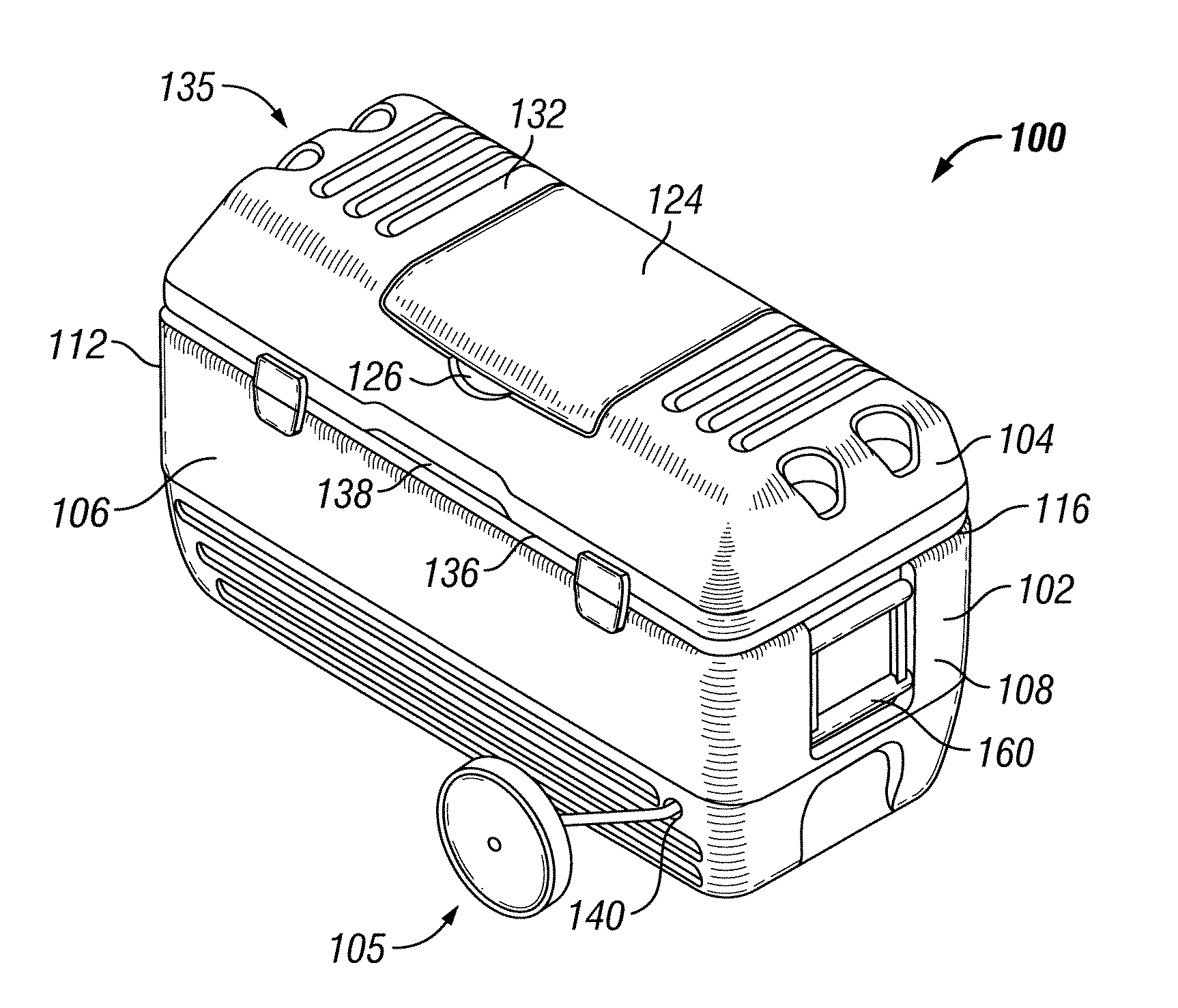
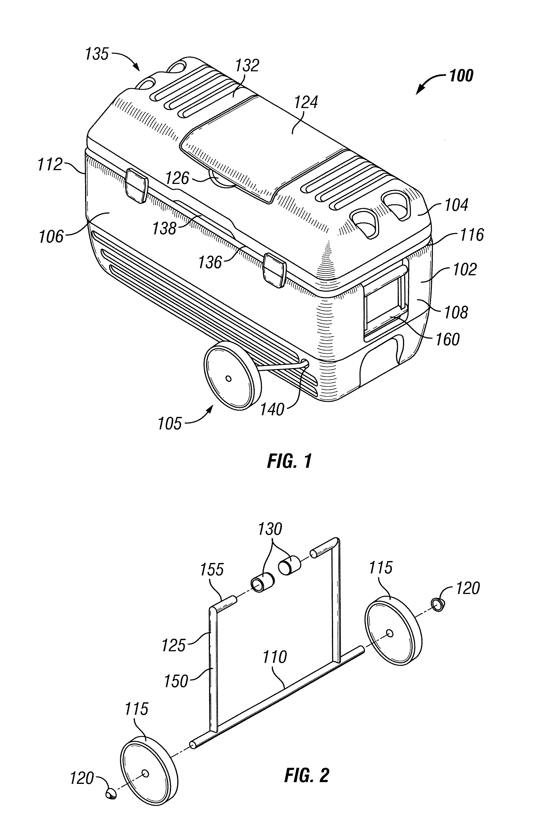
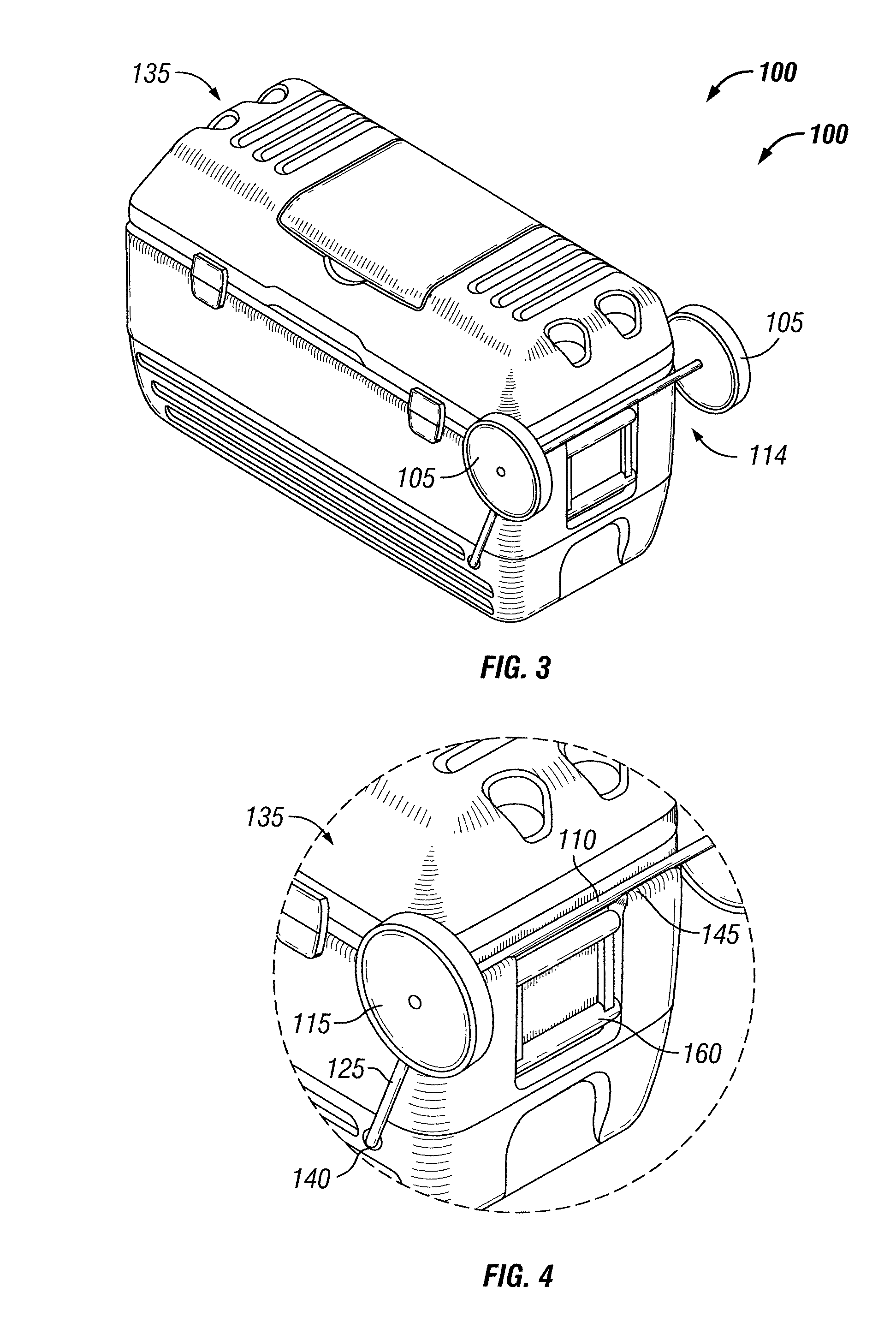
[0021] Exemplary embodiments of the invention will now be described in detail with reference to the included figures. The exemplary embodiments are described in reference to how they might be implemented. In the interest of clarity, not all features of an actual implementation are described in this specification. Those of ordinary skill in the art will appreciate that in the development of an actual embodiment, several implementation-specific decisions must be made to achieve the inventors' specific goals, such as compliance with system-related and business-related constraints which can vary from one implementation to another. Moreover, it will be appreciated that such a development effort might be complex and time-consuming, but would nevertheless be a routine undertaking for those of ordinary skill in the art having benefit of this disclosure. Further aspects and advantages of the various figures of the invention will become apparent from consideration of the following description...


PUM


Abstract

The rotatable wheel assembly includes an axle and wheels. Mounting arms with mounting pins or L-shaped rods are coupled to the axle and may include end caps covering portions of the mounting pin or rod. The mounting pin or end cap is inserted into a receptacle on opposing sides of a cooler. Alternatively, the mounting arms may have an eyelet that may be rotatably coupled to a mounting stud on each side of the cooler. The assembly may be placed in a resting or rolling position along the cooler body. In the resting position, the assembly rests or snaps into a groove along the side of the cooler and out of contact with the surface. The assembly can be rotated from the resting position to a rolling position with the axle positioned under the cooler and the wheels in contact with the surface to assist in transporting the cooler.

Description

STATEMENT OF RELATED PATENT APPLICATION [0001] This non-provisional patent application claims priority under 35 U.S.C. § 119 to U.S. Provisional Patent Application No. 60 / 811,321, titled Rotatable Wheel Assembly for Coolers, filed Jun. 6, 2007. This provisional application is hereby fully incorporated herein by reference.FIELD OF THE INVENTION [0002] This invention relates generally to the field of insulated containers such as coolers or ice chests. More particularly, the present invention relates to a detachable and rotatable wheel assembly for large coolers. BACKGROUND OF THE INVENTION [0003] As the popularity of coolers and ice chests has grown, additional features have been added to enhance their convenience. For small and medium size coolers having a capacity of equal to and less than one hundred quarts, wheels have been added along the bottom of the cooler to enhance their mobility. These wheels are generally fixed to opposing sides of the cooler and extend below the bottom of...

Claims


Application Information

Patent Timeline
Patent Type & Authority Applications(United States)
IPC IPC(8): F25D3/08
CPCA45C5/146A45C11/20B60B3/001B60B35/10F25D2400/38B60B2200/43B60B2310/305F25D3/06B60B35/1009
Inventor VAUGHN, JIM
Owner IGLOO PROD CORP
Why Eureka
Try Eureka