Pixel electrode structure of display device

a display device and electrode structure technology, applied in non-linear optics, instruments, optics, etc., can solve the problems of serious degradation of the display quality of the image displayed by the related art ips mode lcd device and the related art ffs mode lcd device, and achieve the effect of preventing the degradation of the display quality of the imag

Active Publication Date: 2008-01-03
LG DISPLAY CO LTD
View PDF8 Cites 16 Cited by
  • Summary
  • Abstract
  • Description
  • Claims
  • Application Information

AI Technical Summary

Benefits of technology

[0016]An object of the present invention is to provide a pixel electrode structure of a display device and the display device, which are capable of preventing a display quality of an image from being degraded.

Problems solved by technology

Whereas, the TN mode LCD device has a drawback that a viewing angle is not so good due to the refractive index anisotropy of liquid crystals, because the liquid crystal molecules are aligned along an electric field vertically applied thereto.
As a result, the display quality of the image displayed by the related art IPS mode LCD device and the related art FFS mode LCD device can be seriously degraded.

Method used


Image

  • Pixel electrode structure of display device
  • Pixel electrode structure of display device
  • Pixel electrode structure of display device

Examples


Embodiment Construction

[0028]Reference will now be made in detail to the preferred embodiments of the present invention, examples of which are illustrated in the accompanying drawings. Wherever possible, the same reference numbers will be used throughout the drawings to refer to the same or like parts.

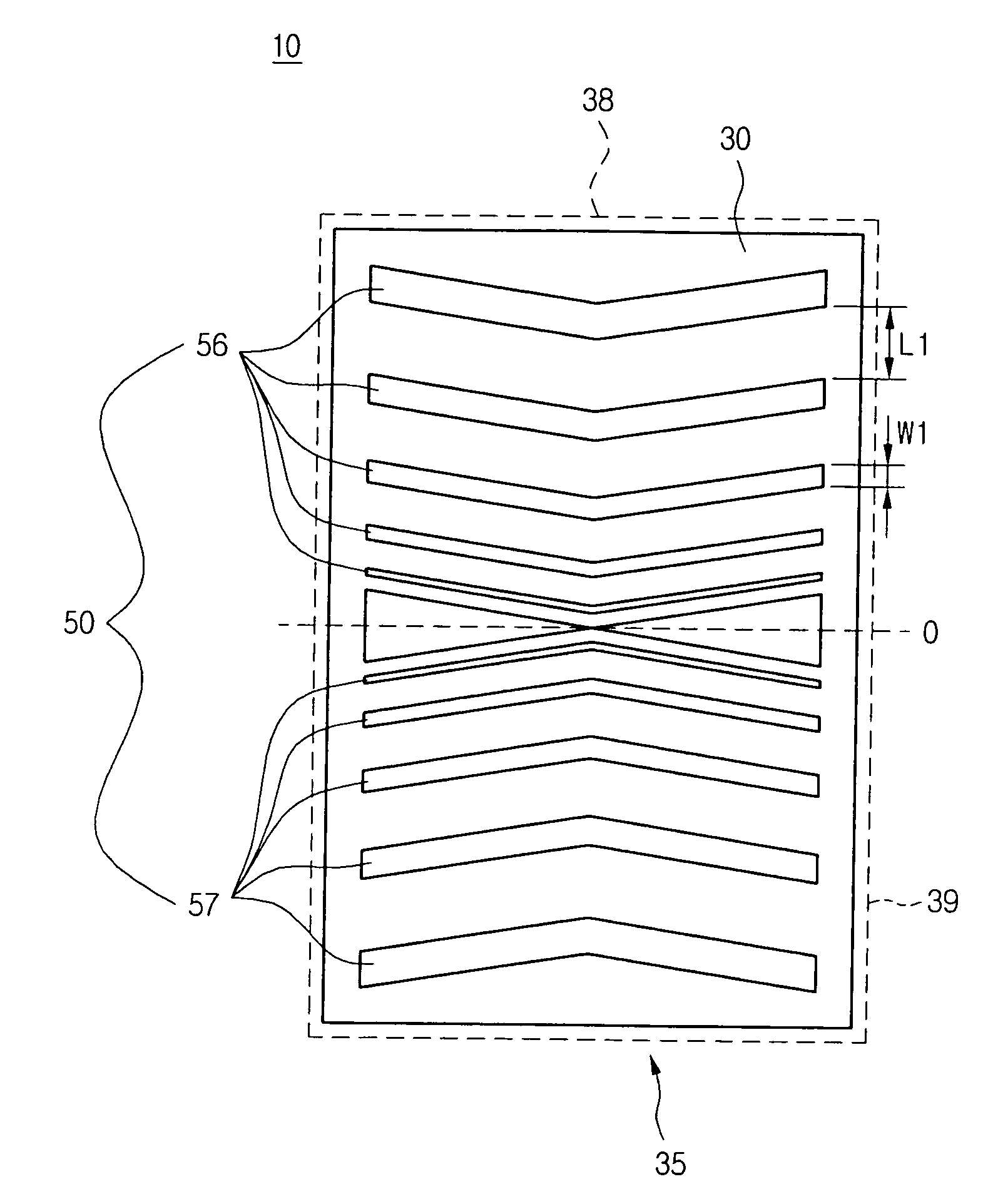
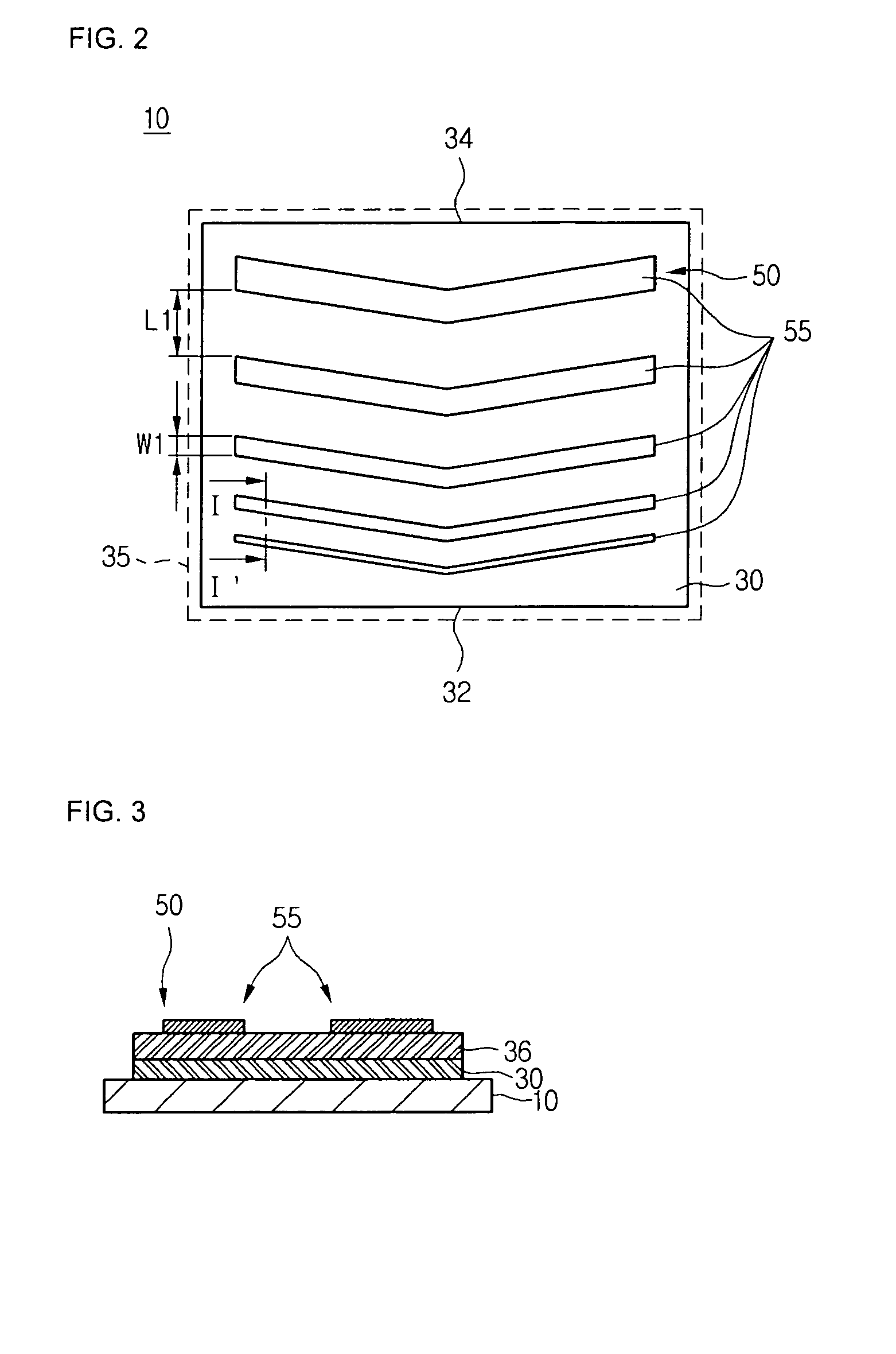
[0029]FIG. 2 is a plan view illustrating a pixel electrode structure of a display device according to one embodiment of the present invention. FIG. 3 is a sectional view taken along the line □-□′ in FIG. 2.

[0030]Referring to FIGS. 2 and 3, a common electrode 30 is formed on a substrate 10. The common electrode 30 may include a transparent conductive layer. The common electrode may be disposed in a pixel region 35. The substrate 10 can be a lower substrate of the display device, such as a TFT array substrate of an IPS mode LCD device. The pixel region 35 can be the display area (or a portion thereof) of the display device.

[0031]An insulating layer 36 may be disposed on the common electrode 30 to cover the com...


PUM

PropertyMeasurementUnit
widthsaaaaaaaaaa
width W1aaaaaaaaaa
width W1aaaaaaaaaa

Abstract

A pixel electrode structure of a display device is discussed. According to an embodiment, the pixel electrode structure includes a plurality of sub pixel electrodes disposed substantially in parallel in the pixel region, wherein the sub pixel electrodes have progressively greater widths and progressively greater spaces therebetween starting from one side of the pixel region to the other opposite side of the pixel region.

Description

[0001]This application claims the priority benefit of Korean Patent Application No. 2006-060207, filed on Jun. 30, 2006, which is hereby incorporated by reference for all purposes as if fully set forth herein.BACKGROUND OF THE INVENTION[0002]1. Field of the Invention[0003]The present invention relates to a pixel electrode structure of a display device. More particularly, the present invention relates to a pixel electrode structure that is adaptive for improving a display quality of an image.[0004]2. Description of the Related Art[0005]In recent years, with the development of an information processing apparatus for processing massive data, a display device that displays the data processed at the information processing apparatus as an image has been actively developed. As the display device, a flat panel display device, representatively such as a liquid crystal display (LCD) device, a plasma display panel (PDP), or an organic light emitting device (OLED) is mainly used.[0006]A twisted...

Claims


Application Information

Patent Timeline
Patent Type & Authority Applications(United States)
IPC IPC(8): G02F1/1343
CPCG02F1/134363G02F1/134309G02F2201/12G02F2001/134372G02F1/134372G02F1/134345G02F1/1343G02F1/133707
Inventor SONG, MOO HYOUNGSHIM, HOAN SU
Owner LG DISPLAY CO LTD
Why Eureka
Try Eureka