Optical module and optical amplification module

a technology of optical amplifier and optical amplifier, which is applied in the direction of optics, optical elements, instruments, etc., can solve the problems of inability to stably supply pump light inability to generate high-power light, etc., and achieve the effect of efficient amplifying, stably providing, and even more stably supply to the optical amplification fiber

Inactive Publication Date: 2008-01-03
MEGAOPTO
View PDF7 Cites 2 Cited by
  • Summary
  • Abstract
  • Description
  • Claims
  • Application Information

AI Technical Summary

Benefits of technology

[0037] In this configuration, the optical fiber for guiding and the other optical fiber for guiding are optically connected to both sides of the optical amplification fiber respectively. And the pump light is supplied to the optical amplification fiber via the optical coupling means and the optical fiber for guiding. The other pump light, which is input to the other optical fiber for guiding through the other optical coupling means, propagates through the third core area and the fifth clad area of the other optical fiber for guiding, and is input to the optical amplification fiber. Since the pump light and the other pump light are input from the optical fiber for guiding and the other optical fiber for guiding to the optical amplification fiber like this, the to-be-amplified light, which is input to the optical amplification fiber via the other optical fiber for guiding, can be efficiently amplified in the optical amplification fiber, and this amplified light can be output to

Problems solved by technology

In this case, the pump light source 40 may be damaged and operation thereof may become unstable, then pump light may not

Method used


Image

  • Optical module and optical amplification module
  • Optical module and optical amplification module
  • Optical module and optical amplification module

Examples


first embodiment

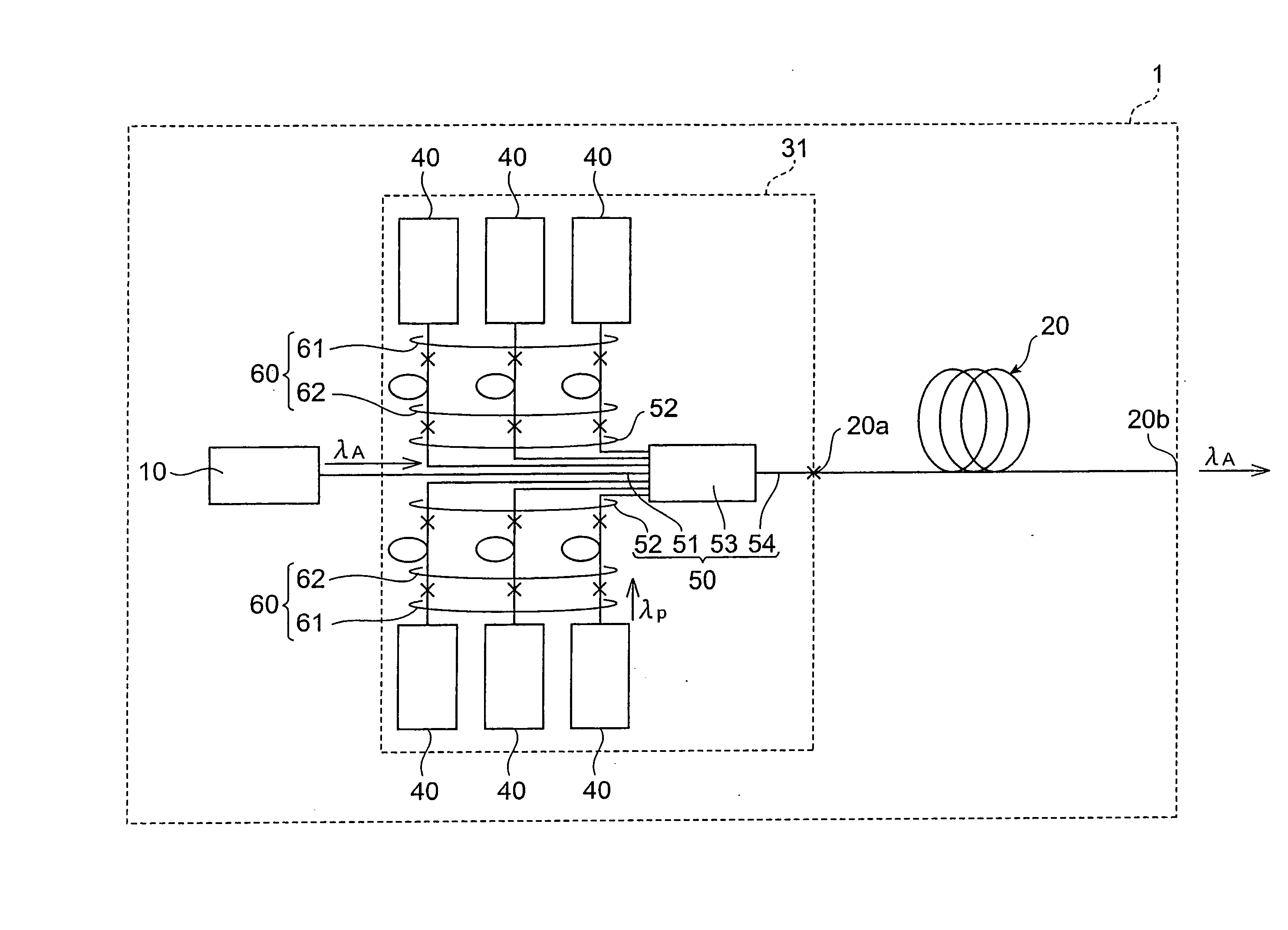
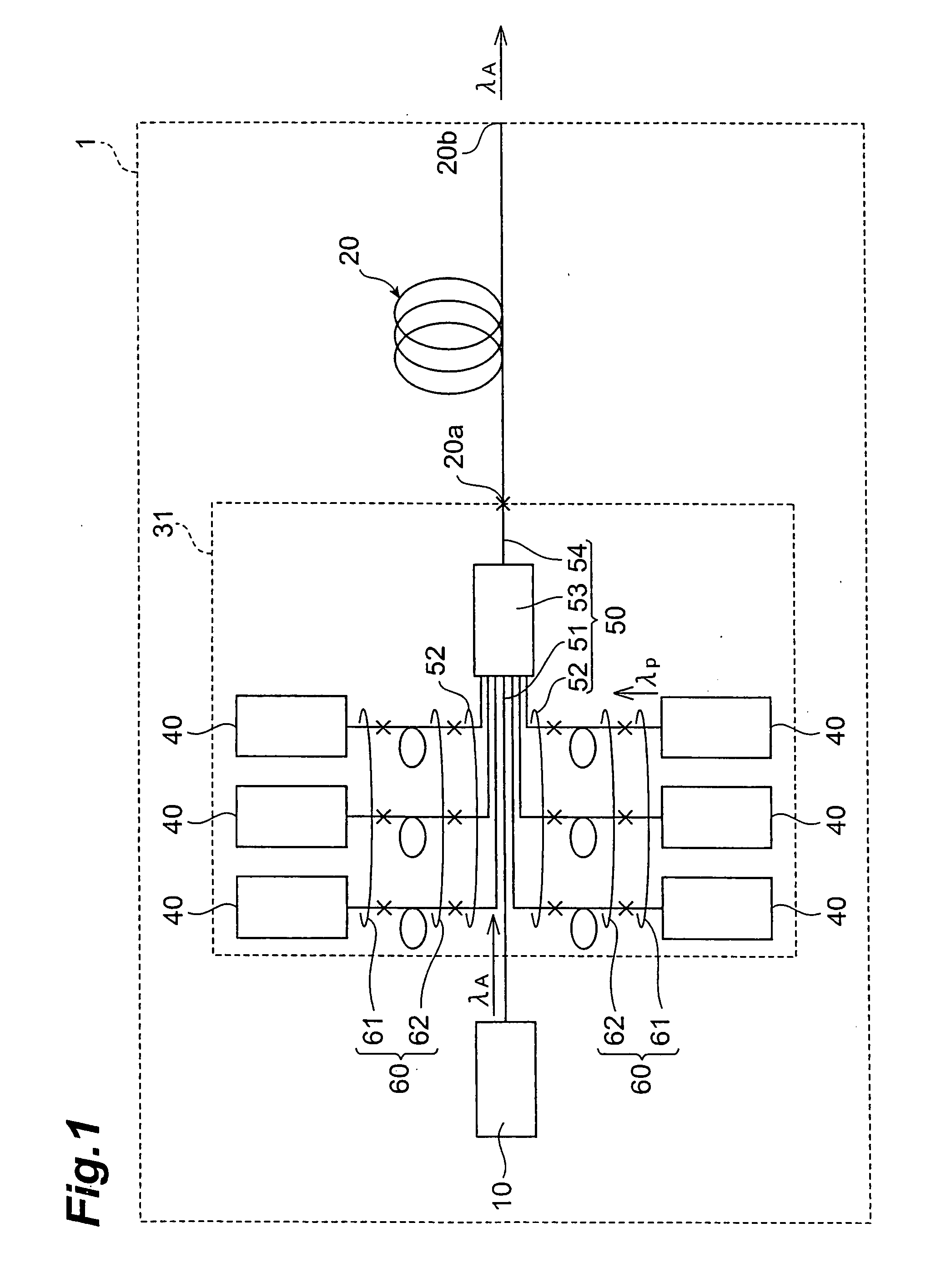
[0060]FIG. 1 is a block diagram depicting a configuration of an optical amplification module according to the first embodiment. The optical amplification module 1 is used as a laser light source of an optical processing system, where an embodiment of the optical module according to the present invention is applied.

[0061] The optical amplification module 1 comprises a light source which outputs a laser beam for processing having wavelength λA as the to-be-amplified light, an optical amplification fiber 20 for optically amplifying the laser beam for processing using an pump light, and an optical module 31 for supplying the laser beam for processing and the pump light to the optical amplification fiber 20. The light source 10 is a laser diode (LD), for example. The light source 10 outputs the laser beam to be amplified as mentioned above.

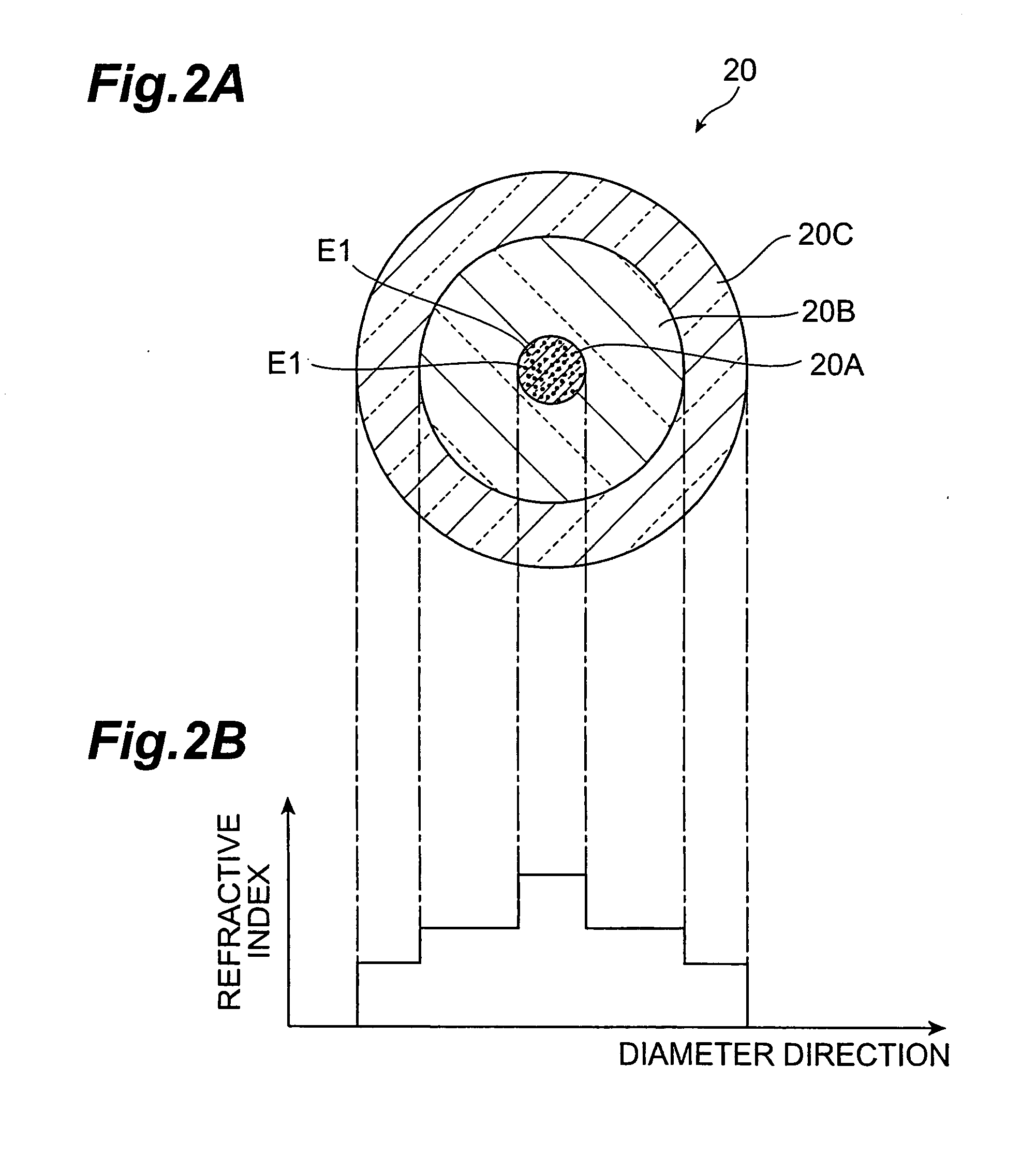
[0062]FIG. 2A is a cross-sectional view depicting the optical amplification fiber sectioned perpendicular to the longitudinal direction. FIG. 2B is ...

second embodiment

[0089]FIG. 8 is a block diagram depicting a configuration of another embodiment of the optical amplification module. The optical amplification module 2 is a back-excitation type optical amplification module.

[0090] In the optical amplification module 2, a light source 10 with a single mode fiber or a LMA (Large Mode Area) fiber is optically connected to an edge section 20a of an optical amplification fiber 20, and a laser beam for processing, which is output from the light source 10, propagates through the optical amplification fiber from the edge section 20a to an edge section 20b. An optical module 32 is optically connected to the edge section 20b of the optical amplification fiber 20.

[0091] Just like the optical module 31 of the first embodiment, the optical module 32 comprises pump light sources 40 and optical coupling means 50, which are optically connected via the optical guide sections 60. In the present embodiment, an optical fiber 54 of the optical coupling means 50 is con...

third embodiment

[0096]FIG. 9 is a block diagram depicting a configuration of another embodiment of the optical amplification module. The optical amplification module 3 is a bidirectional excitation type optical amplification module.

[0097] In the optical. amplification module 3, an optical module 31 is optically connected to an edge section 20a of an optical amplification fiber 20, just like the case of the first embodiment, and an optical module 32 is optically connected to an edge section 20b, just like the case of the second embodiment. A light source 10 is optically connected to an optical fiber 51 of the optical module 31 just like the case of the first embodiment.

[0098] In this configuration, pump lights from pump light sources 40 of each optical module 31 and 32 are input to an optical amplification fiber 20 respectively from the edge sections 20a and 20b, and propagate through the optical amplification fiber 20 and excite the element for optical amplification E1. If a laser beam for proces...


PUM


Abstract

An optical module for supplying pump light for amplifying to-be-amplified light includes an pump light source, optical coupling means, and an optical guide section. The optical guide section optically connects the pump light source and the optical coupling means, and propagates the pump light from the pump light source, in multi-transverse-mode. The optical coupling means output the pump light from the optical guide section in multi-transverse-mode, and at least one of (i) at least one of end faces where the optical guide section and the optical coupling means are connected, (ii) an area between the end faces, and (iii) the optical guide section, has a loss medium of which transmission loss is greater in a wavelength of the to-be-amplified light than in a wavelength of the pump light. By this, an optical module which can stably supply the pump light to the optical amplification fiber can be provided.

Description

CROSS-REFERENCE TO RELATED APPLICATIONS [0001] This application claims propriety to the Provisional Application Ser. No. 60 / 837611 filed on Aug. 15, 2006 by the same Applicant, which is hereby incorporated by reference in its entirety.BACKGROUND OF THE INVENTION [0002] 1. Field of the Invention [0003] The present invention relates to an optical module and an optical amplification module. [0004] 2. Description of the Related Art [0005] Processing technology using a laser beam is receiving attention, and the demand for an optical amplification module that can generate a high power laser beam is increasing in respective fields, including the medical field. For an optical amplification module, a double clad type where an optical fiber in which a rare earth element that can be excited by an pump light is added to the core area is used as an optical fiber for application, is known, as stated in Koji Sugioka and Akira Yabe, “Laser Micro Nano Processing”, First Edition, Japan, CMC Publishin...

Claims


Application Information

Patent Timeline
IPC IPC(8): H01S3/00
CPCG02B6/2804H01S3/06716H01S3/0672H01S3/06729H01S3/1618H01S3/094007H01S3/094053H01S3/09415H01S3/1616H01S3/06758
Inventor TAMAOKI, SHINOBU
Owner MEGAOPTO
Why Eureka
Try Eureka